
Second-level sight line tracing method based on face orientation constraint

A face orientation and gaze tracking technology, applied in the field of human-computer interaction, can solve problems such as shaking the user's head

Active Publication Date: 2017-09-22
SOUTH CHINA NORMAL UNIVERSITY
View PDF7 Cites 54 Cited by
  • Summary
  • Abstract
  • Description
  • Claims
  • Application Information

AI Technical Summary

Problems solved by technology

[0008] The purpose of the present invention is to propose a two-level line of sight tracking method based on face orientation constraints, in order to solve the problem of shaking the user's head in the process of non-intrusive line of sight tracking

Method used


Image

  • Second-level sight line tracing method based on face orientation constraint
  • Second-level sight line tracing method based on face orientation constraint
  • Second-level sight line tracing method based on face orientation constraint

Examples


Embodiment 1

[0053] Such as figure 1 As shown, a two-level gaze tracking method based on face orientation constraints includes the following steps:

[0054] (1) Acquiring an image sequence through a non-invasive image acquisition unit;

[0055] Described step (1) comprises the following steps:

[0056] (1.1) Collect images used by users in real time through the camera and convert them into 256-level grayscale images.

[0057] (1.2) The color space reduction strategy is adopted, the color space is reduced to one thousandth of the original, and the calculation redundancy is reduced.

[0058] (1.3) Use a bilateral filter to preserve and denoise the image.

[0059] (1.4) Gray level equalization enhances image contrast.

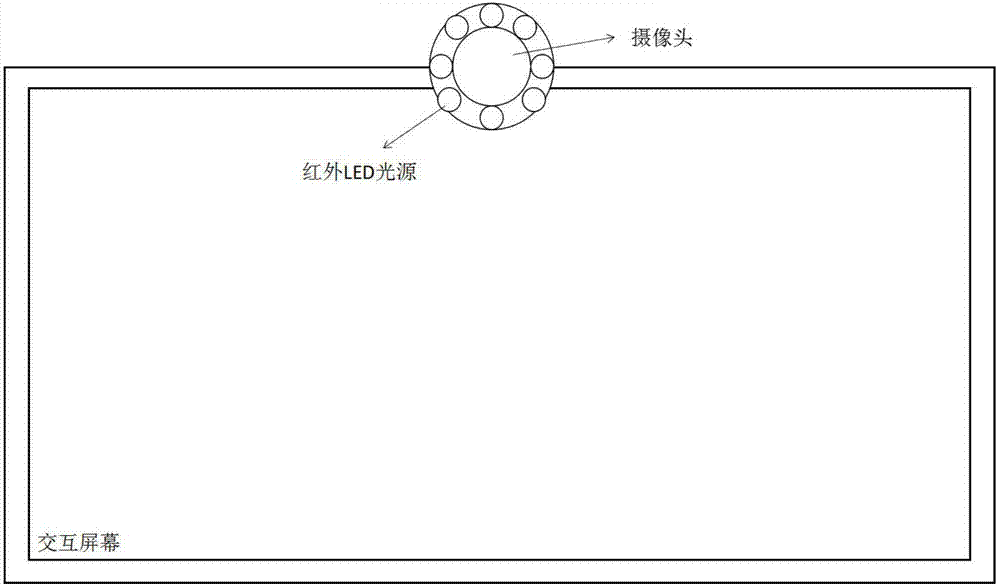
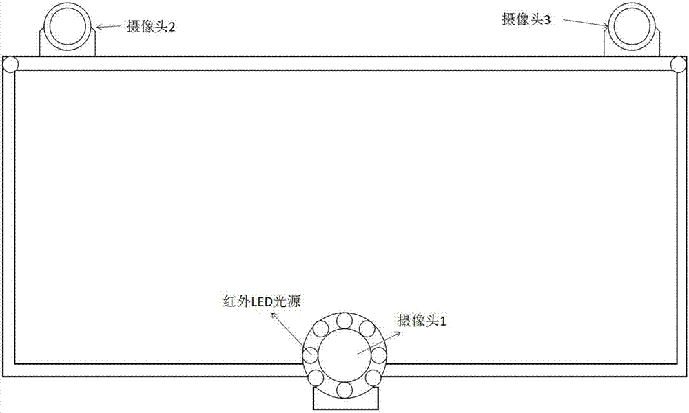
[0060] The human face and eye image acquisition unit is a camera installed near the monitoring screen observed by the user, which is used to photograph the user's face area and obtain images of the user's binocular area. At the same time, the user does not need to wear any ...

Embodiment 2

[0098] What differs from embodiment 1 is that described step (6) comprises following sub-steps:

[0099] (6.1) Based on the method of machine learning, in the face area, detect the eye area falling in the constrained field of view;

[0100] (6.2) Obtain the iris position through the gray scale integral function, then segment the pupil edge in the human eye area based on the Snake model, and locate the pupil center;

[0101] (6.3) Based on the relative position between the pupil center and the eye corner, construct the pupil center-inner corner eye movement vector (Δx, Δy);

[0102] (6.4) Implemented by a classification method: divide the constrained field of view into small intervals and encode them. The system loads the pre-trained artificial neural network, inputs the user's current eye movement information and head posture, and then outputs the current user's gaze hot spot.

[0103] If the method of classification is adopted, further, the constrained field of view is even...


PUM


Abstract

The invention discloses a second-level sight line tracing method based on face orientation constraint. The method comprises the following steps that: obtaining an image sequence; detecting face area and eye area image information; solving a face orientation, taking the face orientation as a ray direction, and defining the ray direction as a standard watching direction; intersecting the ray of the standard watching direction with an equipment screen to obtain a point of intersection, and taking the point of intersection as a standard watching point; taking a screen area delimited by taking the standard watching point as a center as a constraint field of view; and analyzing the eye area image information to obtain the watching area of the user on the constraint field of view. By use of the method, according to the physiologic habits of human eye for observing objects, head shaking is taken as effective sight line tracing information, and a head gesture is preferably considered. By use of the method, a calibration step is omitted, head movement compensation is not required, and true no-constraint sight line tracing can be realized.

Description

technical field [0001] The invention belongs to the technical field of human-computer interaction, and in particular relates to a two-level gaze tracking method based on face orientation constraints. Background technique [0002] Eye movement interaction is an emerging human-computer interaction method in recent years. It uses auxiliary input devices such as eye trackers to use the user's eye movements such as gaze, saccade, and blink as the input of the interactive system, effectively replacing the mouse and keyboard. Eye movement interaction is the most direct and natural way of interaction between humans and machines. Gaze tracking technology is the key and core function to realize human-computer eye movement interaction. The current mainstream implementation methods can be divided into two categories according to whether the user wears a specific optoelectronic device: invasive methods and non-invasive methods. Intrusive methods mainly rely on special optical, electric...

Claims


Application Information

Patent Timeline
IPC IPC(8): G06F3/01G06K9/00
CPCG06F3/013G06F2203/012G06V40/165G06V40/171G06V40/168G06V40/18
Inventor 韩鹏钟颖明邱健骆开庆彭力
Owner SOUTH CHINA NORMAL UNIVERSITY
Learn More