Rotor assembly and permanent magnet motor

A technology for permanent magnet motors and rotors, applied in the direction of magnetic circuit rotating parts, magnetic circuit shape/style/structure, etc., can solve problems such as torque ripple, insufficient motor output, and inability to form air gap flux density

Pending Publication Date: 2017-09-22
ZHUHAI GREE REFRIGERATION TECH CENT OF ENERGY SAVING & ENVIRONMENTAL PROTECTION
View PDF6 Cites 11 Cited by
  • Summary
  • Abstract
  • Description
  • Claims
  • Application Information

AI Technical Summary

Problems solved by technology

[0004] Although this type of motor can significantly reduce the amount of permanent magnets used, thereby greatly reducing the cost of the motor, due to the difference in the materials of adjacent magnetic poles, if it is designed according to a conventional motor, a large air gap flux density cannot be formed on the alternating poles, resulting in The output of the motor is insufficient, and due to the asymmetry of the air gap flux density under the adjacent magnetic poles, a large torque ripple is generated during the operation of the motor

Method used


Image

  • Rotor assembly and permanent magnet motor
  • Rotor assembly and permanent magnet motor
  • Rotor assembly and permanent magnet motor

Examples


no. 1 example

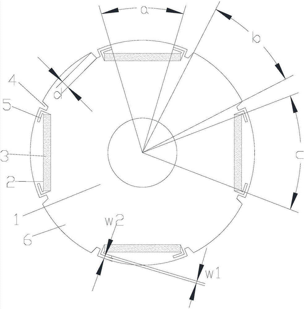
[0043] see in conjunction figure 1 As shown, according to the first embodiment of the present invention, the first air slot 4 extends inwardly from the outer edge of the rotor core 1, the second air slot 5 is located inside the outer peripheral edge of the rotor core 1, and is connected to the mounting slot 2 at the end The parts are connected, and a space is formed between the first air groove 4 and the second air groove 5 . In this embodiment, the installation groove 2 is in a straight shape, and correspondingly, the permanent magnet 3 is also in a straight shape as a whole. This structure can significantly reduce the amount of permanent magnets used, reduce the cost of the motor, and has a larger output and smaller torque ripple.

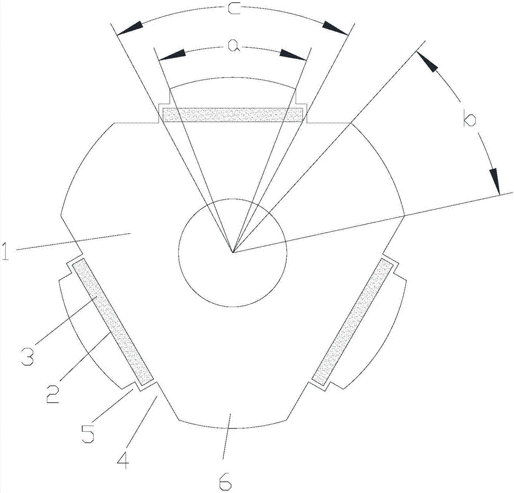
[0044] see in conjunction figure 2 As shown, according to the second embodiment of the present invention, the first air groove 4 extends from the outer edge of the rotor core 1 to the inside, the second air groove 5 extends from the outer edge...


PUM


Abstract

The invention provides a rotor assembly and a permanent magnet motor. The rotor assembly comprises a rotor iron core (1); a plurality of mounting grooves (2) are formed at intervals on the rotor iron core (1) along the circumferential direction; permanent magnets (3) are arranged in the mounting grooves (2); facing the outer peripheral edge of a rotor, each permanent magnet (3) is the same in polarity; the adjacent mounting grooves (2) are separated by soft magnetic materials; first air grooves (4) are formed between both ends of the mounting grooves (2) and the adjacent soft magnetic materials in the circumferential direction of the mounting grooves (2); two second air grooves (5) are formed at one side of each mounting groove (2), which is close to the rotor iron core (1); and one second air groove (5) is formed at a first end of each mounting groove (2), the other second air groove (5) is formed at the second end of the mounting groove (2), and two air grooves extend oppositely. According to the rotor assembly provided by the invention, a large magnetic flux density can be formed in an air gap, motor output is improved, motor efficiency is promoted, and torque fluctuation in the operating process of the motor can be reduced.

Description

technical field [0001] The invention belongs to the technical field of motor equipment, and in particular relates to a rotor assembly and a permanent magnet motor. Background technique [0002] A traditional permanent magnet motor, such as an 8-pole permanent magnet motor, has 8 sets of permanent magnets arranged around the center of the rotor along the direction of rotation, and adjacent permanent magnets have different magnetization directions. The magnetic force lines starting from the N pole of a permanent magnet pass through the stator core to reach the S pole of the adjacent permanent magnet. A flux line passes through at least two permanent magnets in a circuit, so the permanent magnets are underutilized and thus lead to higher costs for the motor. [0003] An alternating pole permanent magnet motor is proposed in the prior art, still taking an 8-pole motor as an example, on which there are only 4 permanent magnet poles, and adjacent permanent magnets have the same l...

Claims


Application Information

Patent Timeline
Patent Type & Authority Applications(China)
IPC IPC(8): H02K1/27
CPCH02K1/2706H02K2213/03
Inventor 胡余生陈彬李权锋孙文娇周博
Owner ZHUHAI GREE REFRIGERATION TECH CENT OF ENERGY SAVING & ENVIRONMENTAL PROTECTION
Why Eureka
Try Eureka