
A Bionic Piezoelectric Pump

A piezoelectric pump and bionic technology, applied in the field of piezoelectric pump research, can solve the problems of large flow and small flow, and achieve the effects of increasing flow and pressure, reducing damage, and reducing pulsation

Active Publication Date: 2019-01-08
JIANGSU UNIV
View PDF6 Cites 0 Cited by
  • Summary
  • Abstract
  • Description
  • Claims
  • Application Information

AI Technical Summary

Problems solved by technology

[0004] The purpose of the present invention is to provide a fully flexible multi-cavity valve valve bionic piezoelectric pump to overcome the shortcomings of traditional piezoelectric pumps with large pulsation and small flow rate.

Method used


Image

  • A Bionic Piezoelectric Pump
  • A Bionic Piezoelectric Pump
  • A Bionic Piezoelectric Pump

Examples


Embodiment Construction

[0036] The present invention will be described in further detail below in conjunction with the accompanying drawings and specific embodiments, but the protection scope of the present invention is not limited thereto.

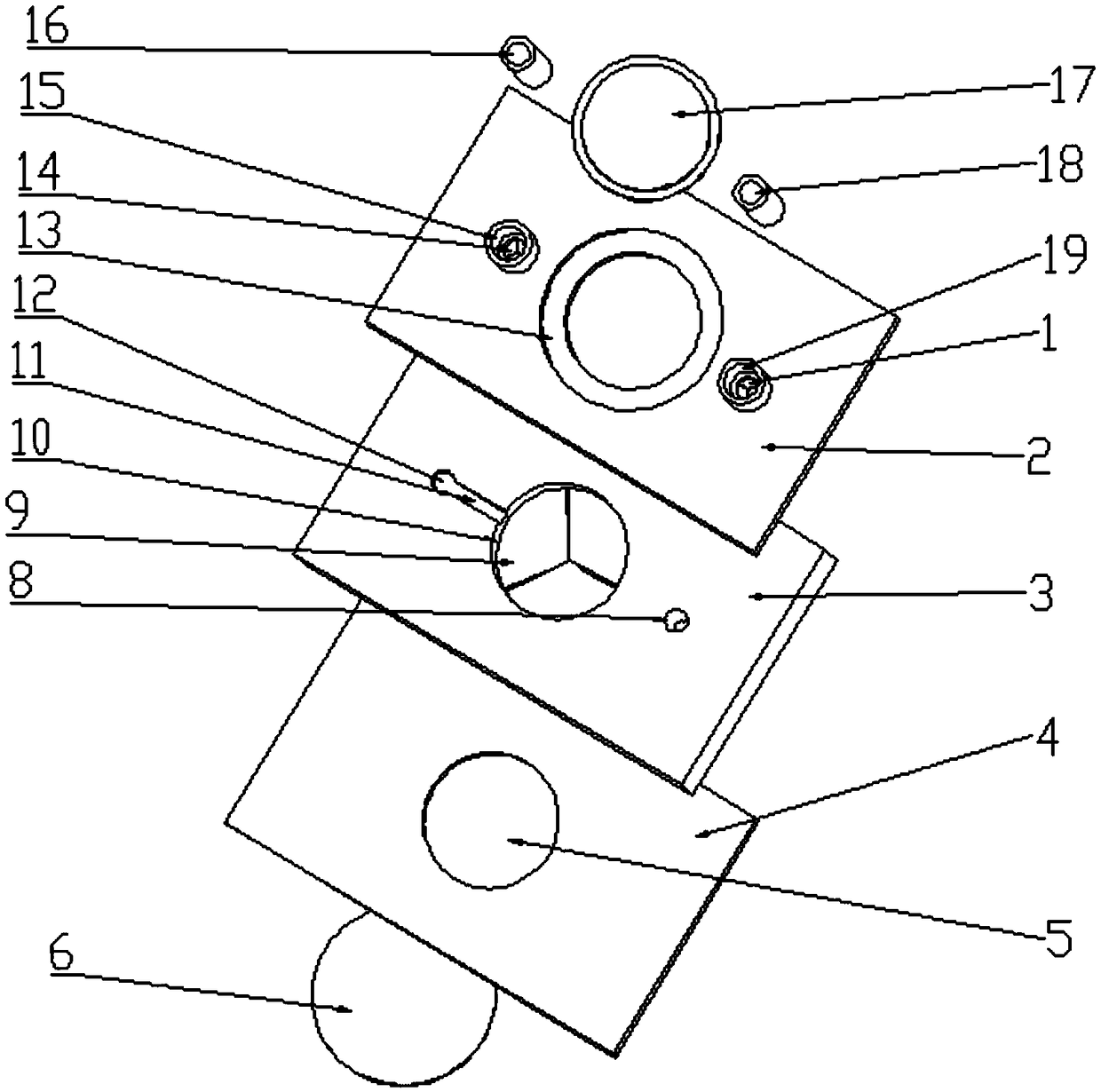
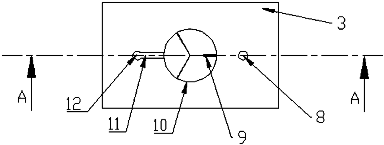
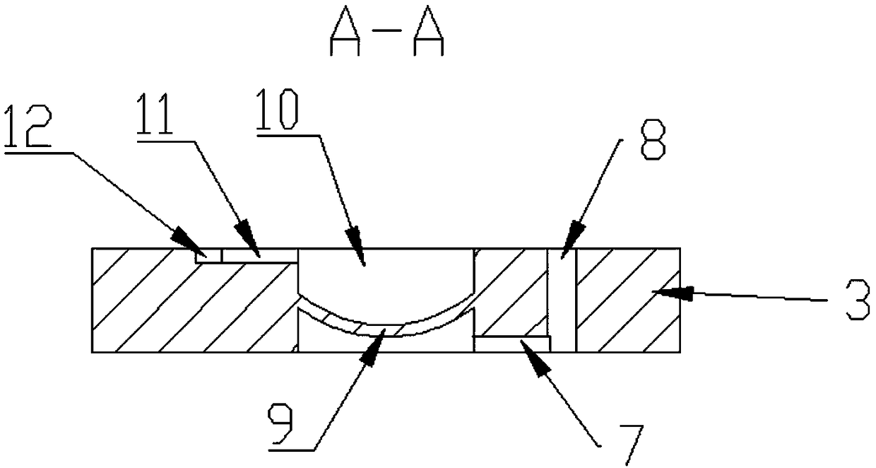
[0037] figure 1 Shown is an embodiment of the bionic piezoelectric pump of the present invention, the bionic piezoelectric pump includes an upper sealing sheet 2, a lower sealing sheet 4, a cavity 3, a water inlet hose 16, and a water outlet hose 18. The flexible piezoelectric driving piece B6 and the flexible piezoelectric driving piece A17. The sealing connection between the upper sealing sheet 2, the lower sealing sheet 4 and the cavity body 3 can be integrally formed by glue bonding or thermal curing. The water inlet hose 16 and the water outlet hose 18 are hermetically connected to the upper sealing sheet 2 respectively, and can be glued to ensure the tightness. The counterbore A13 is sealed and connected to the flexible piezoelectric driving piece A17; t...


PUM


Abstract

The invention provides a bionic type piezoelectric pump. The bionic type piezoelectric pump comprises an upper sealing piece, a lower sealing piece, a cavity, a water inlet hose, a water outlet hose, a flexible piezoelectric driving piece B and a flexible piezoelectric driving piece A. A counter bore A, a water inlet and a water outlet are formed in the upper sealing piece. The water inlet is provided with a valvula valve A, and the water outlet is provided with a valvula valve C. The cavity is provided with a pump cavity, a water inlet connecting pipe, a water outlet connecting pipe, a water inlet water-collection hole and a water outlet water-collection hole. A one-way flowing valvula valve B is arranged in the pump cavity. The counter bore A corresponds to the pump cavity in position and is used for storing the flexible piezoelectric driving piece A. The lower sealing piece is provided with a counter bore B. The counter bore B is used for mounting and bonding the flexible piezoelectric driving piece B therein. According to the bionic type piezoelectric pump, a double-cavity double-vibrator structure is adopted; the pump cavity, the inlet and the outlet are provided with the valvula valves; the heart of a human body is simulated; and the bionic type piezoelectric pump is provided with the multiple pump cavities and the multiple valvula valves, and the capacity and pressure of the pump can be effectively increased. New reference is provided for research of an artificial heart.

Description

technical field [0001] The invention belongs to the field of piezoelectric pump research, in particular to a fully flexible multi-cavity valve bionic piezoelectric pump. Background technique [0002] Driven by a flexible piezoelectric drive plate, the piezoelectric pump realizes the transportation of the medium by periodically changing the volume of the pump chamber. In order to realize the one-way transportation of the medium, increase the pump flow rate and improve the efficiency of pump transportation, a valve can be installed at the pump inlet or outlet, which is called a valved piezoelectric pump. At present, the valves of piezoelectric pumps with valves are generally hard sheets, which change the closed state under the action of pressure difference. Since this kind of valve is a hard sheet, the damage to the conveying medium is relatively large during the opening and closing process, which is not conducive to the transmission of some active media or long molecular cha...

Claims


Application Information

Patent Timeline
Patent Type & Authority Patents(China)
IPC IPC(8): F04B43/04
CPCF04B43/046
Inventor 黄俊田鹏施卫东
Owner JIANGSU UNIV
Learn More