Box girder support mounting trolley

A technology of box girders and trolleys, which is applied to bridges, bridge parts, bridge construction, etc., can solve problems such as safety and quality risks, uneven force on bearings, and impact on quality, so as to reduce safety and quality risks, The effect of reducing equipment investment and good protection

Pending Publication Date: 2017-09-29
CHINA TIESIJU CIVIL ENG GRP CO LTD
View PDF14 Cites 2 Cited by
  • Summary
  • Abstract
  • Description
  • Claims
  • Application Information

AI Technical Summary

Problems solved by technology

The installation of the box girder support is carried out by hoisting and rotation. The anti-rust paint on the surface of the box girder support and the waterproof layer at the beam end will be worn. In severe cases, a large area will fall off and affect the quality.
During the installation process, a single bolt may be deformed and fall off due to the force, which may injure the installer, and there are great risks in terms of safety and quality.
The current support installation wastes manpower and mechanical equipment. The connection and alignment between the top plate on the support and the bolt holes at the bottom of the beam requires manual coordination. For the support in the hoisting state, only one corner of the support can only be aligned with the bolt holes at the bottom of the beam. According to the bolt, a single bolt bears the force, loosen the wire rope, and rotate the support to align with the remaining three bolt holes, so that only one bolt bears the weight of the support, which will easily cause the screw to deform, and the support will fall off and hurt the installer. During the process, the anti-rust paint on the upper roof and the waterproof layer at the beam end will be knocked off, causing quality problems
After the alignment is completed, the oil jacking support is used to fasten the screw. Due to the small contact surface between the oil jacking tray and the support, the force on the support is uneven, which will cause the top plate on the support and the pre-embedded steel plate at the bottom of the beam to be loose. paste

Method used


Image

  • Box girder support mounting trolley
  • Box girder support mounting trolley
  • Box girder support mounting trolley

Examples


Embodiment Construction

[0027] The following will clearly and completely describe the technical solutions in the embodiments of the present invention with reference to the accompanying drawings in the embodiments of the present invention. Obviously, the described embodiments are only some, not all, embodiments of the present invention. Based on the embodiments of the present invention, all other embodiments obtained by persons of ordinary skill in the art without making creative efforts belong to the protection scope of the present invention.

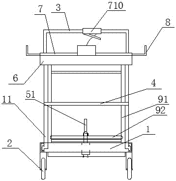
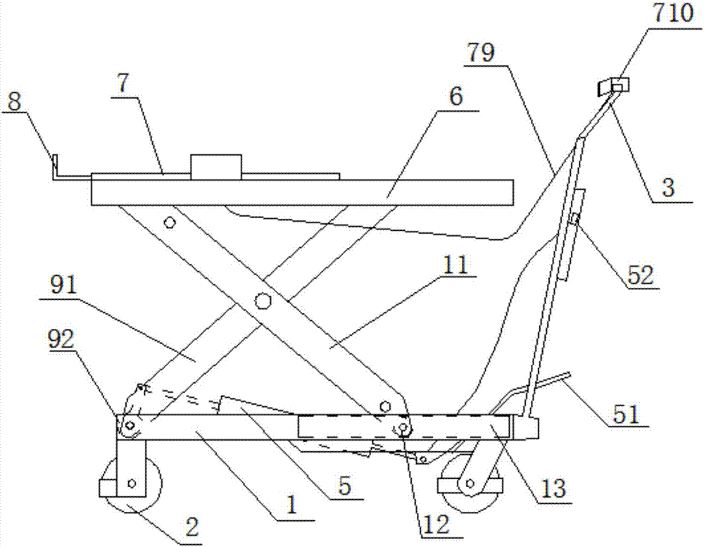
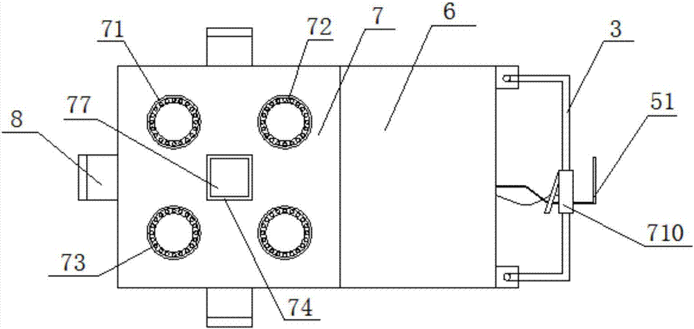
[0028] See Figure 1-Figure 4 , box girder support installation trolley, including a chassis 1, a universal traveling wheel 2 connected to the lower end surface of the chassis 1 with a brake, a U-shaped push armrest 3 connected to the chassis 1, and the bottom end is hinged to the chassis The active lifting frame on 1, the passive lifting frame cross-connected with the active lifting frame through the outrigger connecting beam 4, is fixed on the driving cylind...


PUM


Abstract

The invention discloses a box girder support mounting trolley which comprises a chassis, universal walking wheels, a driving lifting frame, a driven lifting frame, a driving cylinder, a tray, a fine adjustment device and an antiskid device. The universal walking wheels are connected on the lower end surface of the chassis, the bottom end of the driving lifting frame is hinged onto the chassis, the driven lifting frame is connected with the driving lifting frame in an intersected manner, the driving cylinder is fixed on the chassis, the tray is connected at the top end of the driving lifting frame and the driven lifting frame, and the fine adjustment device and the antiskid device are arranged in the tray. According to the trolley, the tray is lifted through the lifting frames, a box girder support is supported by the tray, alignment of the box girder support is adjusted through the fine adjustment device, and the box girder support is firmed through the antiskid device. By the aid of the box girder support mounting trolley, operating efficiency is improved, equipment investment is decreased, safety and quality accidents caused by improper operation are eliminated, and finished products and semi-finished products are effectively protected.

Description

technical field [0001] The invention relates to the field of bridge engineering construction, in particular to a trolley for installing a box girder support. Background technique [0002] The current box girder supports are mostly installed with forklifts. The truck-mounted cranes and forklifts cooperate with steel wire ropes to hoist the box girder supports for support installation. Align remaining bolt holes by rotating. The installation of the box girder support by hoisting and rotation will cause wear to the anti-rust paint on the surface of the box girder support and the waterproof layer at the beam end. In severe cases, it will cause a large area to fall off and affect the quality. During the installation process, a single bolt may be deformed and fall off due to the force, and the installer may be injured. There are great risks in terms of safety and quality. The current support installation wastes manpower and mechanical equipment. The connection and alignment betw...

Claims


Application Information

Patent Timeline
Patent Type & Authority Applications(China)
IPC IPC(8): E01D21/00E01D19/04
CPCE01D21/00E01D19/04
Inventor 姚东升管新权张晓亮李仓华史浩浩葛明祥赵万林
Owner CHINA TIESIJU CIVIL ENG GRP CO LTD
Why Eureka
Try Eureka