
None-motile pressure relieving plate with drainage function for nuclear power unit

A nuclear power unit, passive technology, applied in the direction of functional valve types, mechanical equipment, engine components, etc., can solve the problem that the passive pressure relief plate has a single structure, cannot effectively block the spread of fire, and the pressure relief plate cannot perform the function of draining water, etc. problems, to achieve the effect of blocking the spread of fire

Active Publication Date: 2017-09-29
江苏华洋新思路能源装备股份有限公司
View PDF7 Cites 2 Cited by
  • Summary
  • Abstract
  • Description
  • Claims
  • Application Information

AI Technical Summary

Problems solved by technology

[0002] At present, the structure of the passive pressure relief plate used in nuclear power units is relatively simple. When the indoor air or steam pressure exceeds the design pressure, the pressure relief plate cannot release the pressure of the indoor air or steam in time; The existing pressure relief plate cannot perform the function of draining water. At the same time, when a fire breaks out in the room, the current pressure relief plate cannot effectively block the spread of the fire source.

Method used


Image

  • None-motile pressure relieving plate with drainage function for nuclear power unit
  • None-motile pressure relieving plate with drainage function for nuclear power unit
  • None-motile pressure relieving plate with drainage function for nuclear power unit

Examples


Embodiment Construction

[0033] The present invention will be described in detail below in conjunction with the accompanying drawings and embodiments.

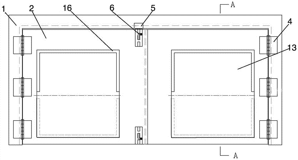
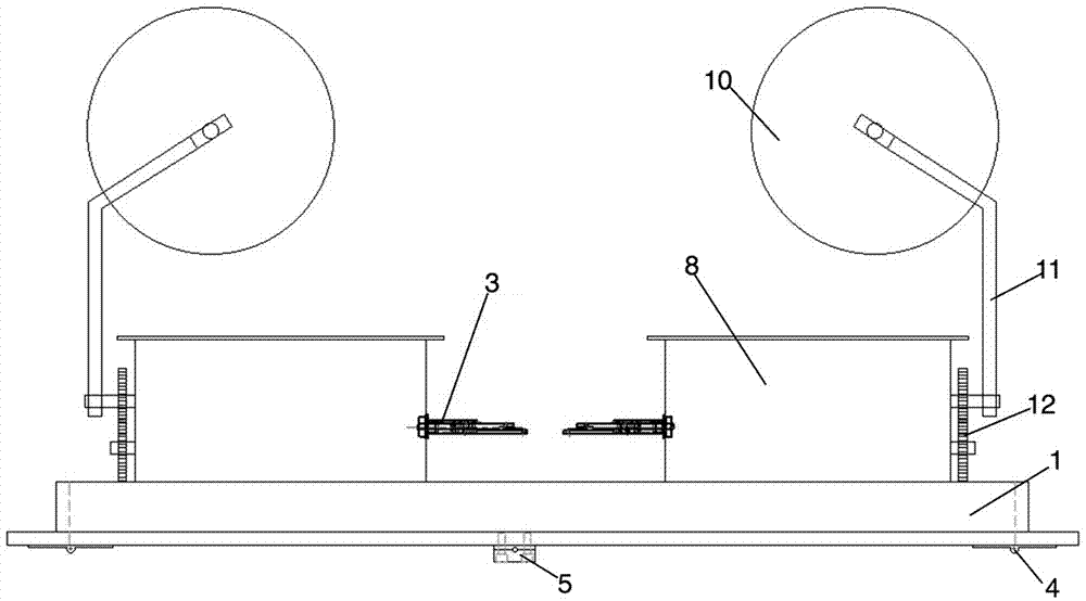
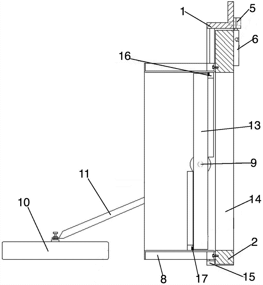
[0034] Such as Figure 1-15As shown: this embodiment is a passive pressure relief plate with drainage function for nuclear power units, including a frame 1, a door panel 2, a drain assembly and a fusible bolt 3, wherein the door panel 2 is rotatably connected to the frame 1 through a hinge 4 , the door panel 2 is provided with a shear bolt assembly, and the frame 1 is provided with a bolt fixing seat 5 corresponding to the shear bolt assembly. Cut the bolt 7, under the locked state of the door panel 2, the shear bolt 7 is plugged into the bolt fixing seat 5, and the drain assembly is arranged on the inner side of the door panel 2, and the drain assembly includes a drain frame 8, a blade shaft 9, a floating The ball 10, the floating ball rod 11 and the transmission gear set 12, the blade shaft 9 is arranged inside the drain frame 8, and the two ends o...


PUM


Abstract

The invention discloses a none-motile pressure relieving plate with a drainage function for a nuclear power unit. The pressure relieving plate comprises a frame, door planks, water releasing assemblies and fusible bolts; the door planks are provided with shearing bolt assemblies, the frame is provided with a bolt fixing seat, and shearing bolts in the shearing bolt assemblies are inserted into the bolt fixing seat; the water releasing assemblies are arranged on the inner side faces of the door planks, and each water releasing assembly comprises a blade shaft, a floating ball, a floating ball rod and a transmission gear set; and the two ends of the blade shafts are in transmission connection with the two sides of water releasing frames, the blade shafts are provided with blades, the planks are provided with water releasing channels corresponding to the blades, the floating balls are connected with the floating ball rods, the floating ball rods are furthermore in transmission connection with the blade shafts through transmission gear sets, the floating balls move up and down to drive the floating ball rods to poke the transmission gear sets to rotate the blade shafts, the blade shafts are rotated to make the blades open or close the water releasing channels on the door planks, and the water releasing frames are provided with the fusible bolts. The pressure relieving plate has the pressure relieving function and also has the water releasing and fire prevention functions.

Description

technical field [0001] The invention relates to a pressure relief plate for a nuclear power unit, in particular to a passive pressure relief plate with drainage function for a nuclear power unit, belonging to the technical field of nuclear power equipment. Background technique [0002] At present, the structure of the passive pressure relief plate used in nuclear power units is relatively simple. When the indoor air or steam pressure exceeds the design pressure, the pressure relief plate cannot release the pressure of the indoor air or steam in time; The existing pressure relief plate cannot perform the function of draining water. At the same time, when a fire breaks out in the room, the current pressure relief plate cannot effectively block the spread of the fire source. Contents of the invention [0003] In order to solve the deficiencies of the prior art, the present invention provides a passive pressure relief plate with drainage function for nuclear power units, so th...

Claims


Application Information

Patent Timeline
Patent Type & Authority Applications(China)
IPC IPC(8): F16K17/14F16K17/38F16K31/18
CPCF16K17/14F16K17/38F16K31/18
Inventor 吴桂章王泽超刘莉莉
Owner 江苏华洋新思路能源装备股份有限公司
Learn More