Driving photographing system and method and device thereof
A camera system and camera technology, applied in the field of driving camera systems, can solve problems such as blurred lenses and inability to improve camera image effects
- Summary
- Abstract
- Description
- Claims
- Application Information
AI Technical Summary
Problems solved by technology
Method used
Image
Examples
Embodiment 1
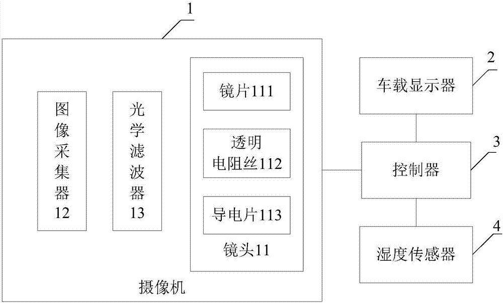
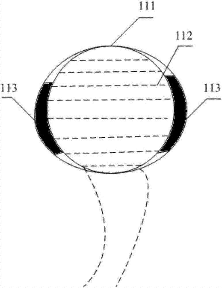
[0027] An embodiment of the present invention provides a driving camera system, such as figure 1 As shown, including: camera 1, humidity sensor 2, vehicle display 3, controller 4, controller 4 is connected with camera 1, humidity sensor 2, vehicle display 3,
[0028] Wherein the camera 1 converts the optical image signal into an electrical signal for storage or transmission. When we shoot an object, the light reflected on the object is collected by the lens of camera 1, making it focus on the light-receiving surface of the imaging device (such as the target surface of the imaging tube), and then the light is converted into electrical energy by the imaging device, that is, "Video signal".
[0029] The camera 1 in this embodiment is used to capture images in vehicles to form a driving camera system to help drivers view image information around the vehicle, which is conducive to safe driving. This camera 1 is arranged on the license plate side of the vehicle rear, and towards t...
Embodiment 2
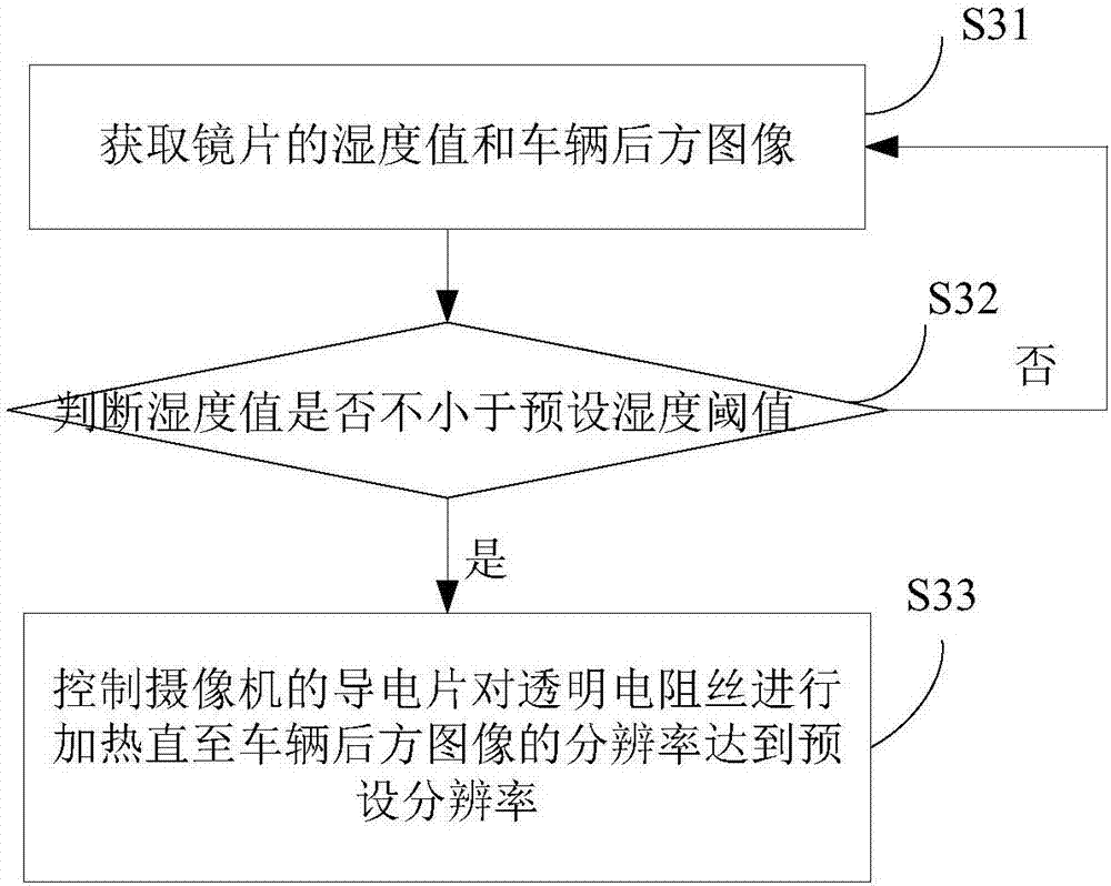
[0040] An embodiment of the present invention provides a driving camera method, which is used in the driving camera system in Embodiment 1, such as image 3 shown, including the following steps:
[0041] S31. Obtain the humidity value of the lens and the rear image of the vehicle. For example: the humidity sensor detects that the humidity value on the lens on the camera is 10%, and the rear image of the vehicle includes the license plate number of the vehicle behind, the color of the vehicle behind, and trees or buildings around the rear, etc.
[0042] S32. Determine whether the humidity value is not less than a preset humidity threshold. The preset humidity threshold here is a preset humidity reference threshold based on application scenarios and different seasons, so as to facilitate judging whether the humidity on the lens reaches the reference value. For example: the preset humidity threshold is 5%. However, the humidity value on the lens detected in step S21 is 10%, sin...
Embodiment 3
[0047] This embodiment provides a driving camera device, such as Figure 4 Shown, be used in the driving camera system in embodiment 1, comprise:
[0048] Obtaining module 41, for obtaining the humidity value of camera lens and vehicle rear image;
[0049] Judging module 42, used to judge whether the humidity value is not less than the preset humidity threshold;
[0050] The control module 43 is used to control the conductive sheet of the camera to heat the transparent resistance wire until the resolution of the image behind the vehicle reaches the preset resolution when the humidity value is not less than the preset humidity threshold.
[0051] as an optional implementation. In the driving camera device in this embodiment, the preset resolution is set according to the image that can be recognized by the driver's normal eyesight according to different light intensities.
[0052] In the driving camera method in this embodiment, when the driver is driving in rainy or foggy da...
PUM
 Abstract
Description
Claims
Application Information
 - R&D
- Intellectual Property
- Life Sciences
- Materials
- Tech Scout
- Unparalleled Data Quality
- Higher Quality Content
- 60% Fewer Hallucinations
Browse by: Latest US Patents, China's latest patents, Technical Efficacy Thesaurus, Application Domain, Technology Topic, Popular Technical Reports.
© 2025 PatSnap. All rights reserved.Legal|Privacy policy|Modern Slavery Act Transparency Statement|Sitemap|About US| Contact US: help@patsnap.com


