Tire valve

A tire valve and valve seat technology, applied in the field of tire valves, can solve the problems of difficult dual airway arrangement, limited deflation speed, and limited deflation speed, so as to shorten execution time, fast deflate speed and prolong The effect of service life

Inactive Publication Date: 2017-10-03
CHONGQING YANZHAO AUTOMOBILE TECH
View PDF7 Cites 0 Cited by
  • Summary
  • Abstract
  • Description
  • Claims
  • Application Information

AI Technical Summary

Problems solved by technology

In the prior art, the tire valve deflated along the pipeline needs to have a certain gas pressure in the pipeline to ensure that the tire valve is in the open state. This throttling and deflation method greatly limits the The speed of deflation makes the time required for the deflation process longer; in view of the fact that springs are generally used as elastic return elements of the valve clack in traditional structures, the size of the valve port is also limited due to the limitation of the size of the spring, and the valve port is too small. The speed of deflation is limited; in the system using dual air channels, the tire valve is fully open in the deflated state, but the arrangement of the dual air channels is more difficult, corresponding to each wheel needs to add a pair of Rotate to seal the air chamber, so the reliability of the system will be less

Method used


Image

  • Tire valve
  • Tire valve
  • Tire valve

Examples


Embodiment Construction

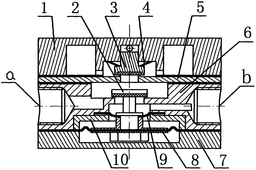
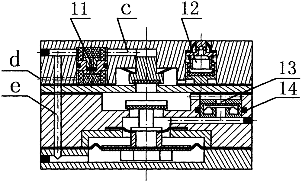
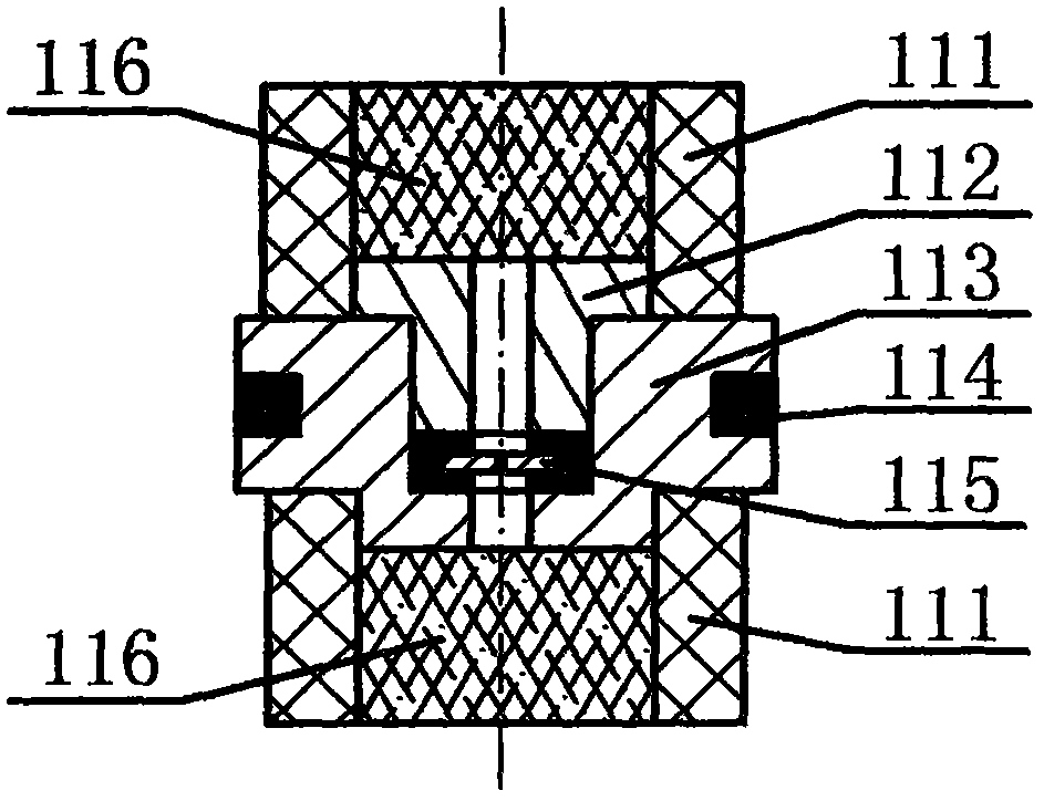
[0028] Below in conjunction with accompanying drawing, the present invention is further elaborated:

[0029]A tire valve, mainly comprising a valve body (1), a main valve disc (2), a one-way valve disc (3), a one-way valve return spring (4), a one-way valve seat (5), a main valve seat ( 6), valve bottom (7), second diaphragm (8), first diaphragm (9), spacer ring (10), delayed air release valve (11), low pressure exhaust valve (12) and inflation valve ( 13) and other components; the main valve seat (6) is divided into upper and lower chambers and is provided with a main valve port communicating with the upper chamber and the lower chamber, and the main valve seat (6) The lower chamber is further divided into upper and lower stepped holes arranged on the coaxial line, and the side wall of the main valve seat (6) is respectively provided with an air inlet (a) communicating with the upper chamber and An air outlet (b) communicating with the upper stepped hole of the lower chamber...


PUM


Abstract

The invention relates to a tire valve. The tire valve mainly comprises components such as a valve body, a check valve seat, a main valve seat, a valve bottom, a check valve clack, a main valve clack, check valve reset springs, a first diaphragm, a spacer ring, a second diaphragm, a delayed release valve, a low-pressure exhaust valve, an inflation valve and the like; an air inlet and an air outlet are formed in the main valve seat; a stepped hole and an air storage cavity are formed in the valve body; the check valve seat is mounted on the main valve seat; the valve body is mounted on the check valve seat; the check valve clack is mounted on the check valve seat; the check valve clack and the check valve seat form a sealing pair; the main valve clack and the main valve seat form a sealing pair; both the first diaphragm and the second diaphragm are mounted on the main valve seat and the main valve clack; the inflation valve is arranged on the main valve seat; the delayed release valve and the low-pressure exhaust valve are arranged in the valve body; and the tire valve further comprises a first air channel, a second air channel, an exhaust hole and a through hole. The valve opening of the tire valve has the large drift diameter and has the large opening degree during deflation, so that the deflation speed is greatly increased, and the survival ability of a military off-road vehicle in the battlefield is improved.

Description

technical field [0001] The invention relates to a control valve in a tire central inflation and deflation system of a military off-road vehicle, in particular to a tire valve. Background technique [0002] The tire central inflation and deflation system of off-road vehicles is mainly used to improve passability and off-road ride comfort. It is mainly composed of tire valves, rotating sealed air chambers, lock valves, and steering control devices. [0003] The tire valve is one of the core components of the tire central inflation and deflation system. It is installed on the wheel and rotates with the wheel. It is mainly used to isolate the gas passage between the tire air chamber and the rotating sealing air chamber, so that the rotating sealing air chamber It does not bear the effect of gas pressure when the tire is under pressure, so as to prolong the service life of the rotating sealed air chamber. [0004] The tire valve is a key component in the central inflation and de...

Claims


Application Information

Patent Timeline
Patent Type & Authority Applications(China)
IPC IPC(8): F16K15/18F16K15/20
CPCF16K15/202F16K15/1826
Inventor 刘艳昭
Owner CHONGQING YANZHAO AUTOMOBILE TECH
Why Eureka
Try Eureka