Spiral scanning measurement track planning method for cylindrical curved surface

A trajectory planning and spiral technology, which is applied in the field of spiral scanning measurement trajectory planning, can solve the problem that the effect of improving measurement efficiency is not obvious

Active Publication Date: 2017-10-03
HUAZHONG UNIV OF SCI & TECH +1
View PDF5 Cites 17 Cited by
  • Summary
  • Abstract
  • Description
  • Claims
  • Application Information

AI Technical Summary

Problems solved by technology

The measurement efficiency can be improved by increasing the width of the measurement area to reduce the number of measurement areas, but the width of the measurement

Method used


Image

  • Spiral scanning measurement track planning method for cylindrical curved surface
  • Spiral scanning measurement track planning method for cylindrical curved surface
  • Spiral scanning measurement track planning method for cylindrical curved surface

Examples


Embodiment Construction

[0124] The present invention will be further described below in conjunction with the accompanying drawings and embodiments.

[0125] Such as Figure 9 As shown, the present invention includes (1) forming an offset curved surface S r Step; (2) offset surface S r Triangulation step; (3) triangulation offset surface S t Parameterization step; (4) planning guide line and interval line step; (5) calculating spiral guide line G (t) and spiral interval line E (t) step; (6) calculating guide trajectory C (t) step; (7 ) Step of generating swing trajectory reference scan curve; (8) Step of generating swing scan trajectory P(t).

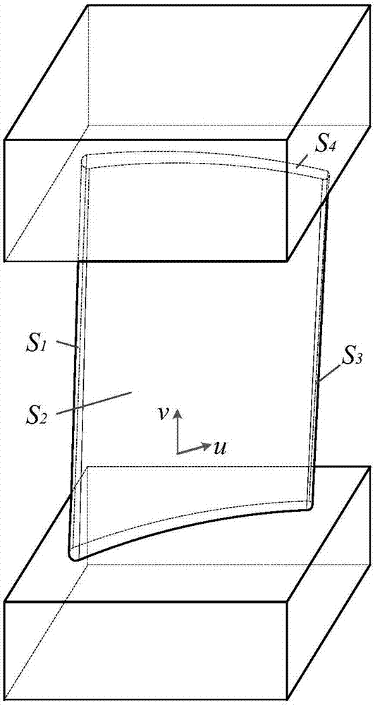
[0126] As an embodiment, the composite curved surface formed by the leading edge, blade basin, trailing edge, and blade back in the aviation blade is selected as the cylindrical curved surface to be measured, and the CAD three-dimensional model of the aviation blade is as follows Figure 10 shown. Due to the large curvature at the leading edge and trailing...


PUM


Abstract

The invention, which belongs to the technical field of curved surface coordinate measurement, provides a spiral scanning measurement track planning method for a cylindrical curved surface, thereby improving the measurement efficiency of cylindrical parts by reducing non-measurement movement time of a measuring head and the length of a guiding track C(t). The method comprises steps of an offset curved surface Sr forming step, a offset curved surface Sr triangularization step, a triangularized offset curved surface Sr parameterization step, a guiding line and spacing line planning step, a spiral guide line G(t) and a spiral spacing line E(t) calculating step, a guiding track C(t) calculating step, an oscillating track parameter scanning curve generation step, and an oscillating scanning track P(t) generation step. The measurement process can be completed by one reciprocating scanning movement of a pointed head of a probe of a measuring head, so that the non-measurement movement time of the measuring head and the length of the guiding track C(t) during the cylindrical curved surface measurement process are reduced and thus the measurement efficiency of the cylindrical curved surface is improved.

Description

technical field [0001] The invention belongs to the technical field of curved surface coordinate measurement, and in particular relates to a spiral scanning measurement trajectory planning method for cylindrical curved surfaces. technical background [0002] A cylindrical surface refers to a composite surface composed of N surfaces, N≥1, N is determined by its CAD design model, thus determining that the cylindrical surface has N generatrices, and the section line of the composite surface is a closure with continuous first-order derivatives Curves, such as hyperboloids, frustum sides, cylinder sides, and their arbitrarily deformed G1 continuous surfaces, such as figure 1 The aero blade shown is defined by the leading edge S 1 , leaf pot S 2 , trailing edge S 3 , Yebei S 4 form cylindrical surfaces. The generatrix refers to the connecting line of adjacent curved surfaces in the compound curved surface, and the G1 continuous curved surface refers to that the first-order de...

Claims


Application Information

Patent Timeline
IPC IPC(8): G01B5/008G01B7/008G01B21/04
CPCG01B5/008G01B7/008G01B21/04
Inventor 胡鹏程李雷周会成李振瀚陈吉红邹碧康
Owner HUAZHONG UNIV OF SCI & TECH
Why Eureka
Try Eureka