Centrifugal compression type dehydrator

A technology of centrifugal compression and dehydration machine, which is applied in spin dryers, washing devices, textiles and papermaking, etc. It can solve the problems of reducing the working stability of dehydration machines, insufficient heat dissipation performance, and insufficient dehydration efficiency, so as to speed up the dehydration rate. , increase the size of the force, prolong the effect of service life

Inactive Publication Date: 2017-10-10
CHENGDU YANXINGGUO TECH CO LTD
View PDF0 Cites 0 Cited by
  • Summary
  • Abstract
  • Description
  • Claims
  • Application Information

AI Technical Summary

Problems solved by technology

[0003] However, the existing dehydration machines have some shortcomings during use. On the one hand, the dehydration efficiency is not fast enough, and on the other hand, the heat dissipation performance is not strong enough, which reduces the working stability of the dehydration machine.

Method used


Image

  • Centrifugal compression type dehydrator
  • Centrifugal compression type dehydrator

Examples


Embodiment Construction

[0018] The following will clearly and completely describe the technical solutions in the embodiments of the present invention with reference to the accompanying drawings in the embodiments of the present invention. Obviously, the described embodiments are only some, not all, embodiments of the present invention.

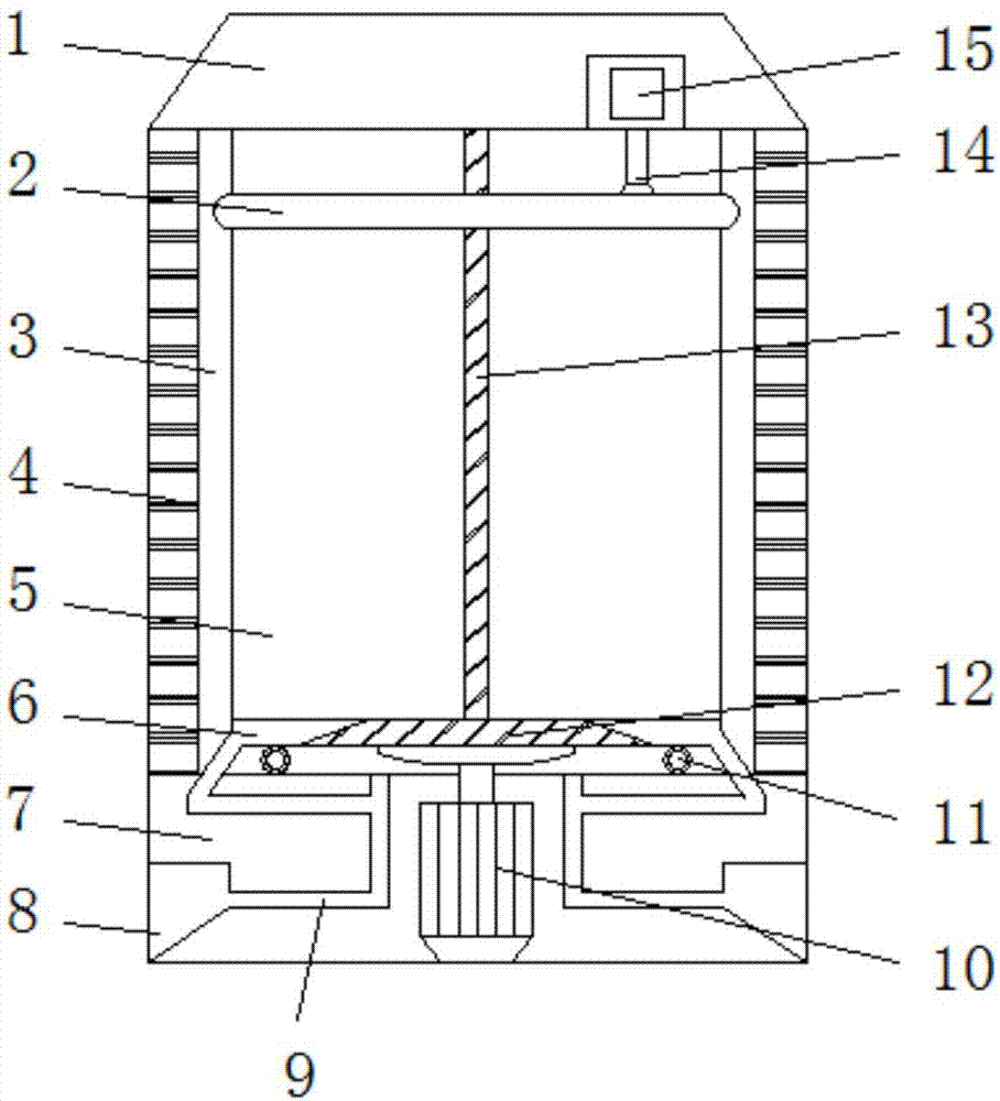
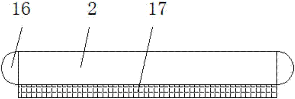
[0019] refer to Figure 1-2 , a centrifugal compression dehydrator, including a dehydration bin 5, a sealed bin 1 is arranged on the top of the dehydration bin 5, and a YQ-telescopic cylinder 15 is arranged inside the sealed bin 1, and the YQ-telescopic cylinder 15 connects with the dehydration bin through a hydraulic telescopic rod 14 5. The pressure plate 2 on the inner surface wall is connected, the sliding head 16 is welded on both sides of the pressure plate 2, the water barrier 17 is welded on the bottom of the pressure plate 2, the inner surface of the dehydration chamber 5 is provided with a guide rail 3, and the two sides of the dehydration chamber 5 are prov...


PUM


Abstract

The invention discloses a centrifugal compression dehydrator, which comprises a dehydration bin, a sealed bin is arranged on the top of the dehydration bin, and a YQ-telescopic cylinder is arranged inside the sealed bin, and the YQ-telescopic cylinder is connected to the dehydration bin through a hydraulic telescopic rod. The pressure plate on the inner surface wall is connected, the two sides of the pressure plate are welded with sliders, the bottom of the pressure plate is welded with a water barrier, the inner surface of the dehydration chamber is provided with a guide rail, the bottom of the dehydration chamber is welded with a base, and the center of the base is A motor is provided at the center, and the motor passes through the elastic plate through the rotating shaft to drive and connect with the dehydration chamber. There are water leakage holes on both sides of the bottom of the dehydration chamber, and the leakage holes are connected to the water collection chamber inside the base through the water guide pipe. The dehydration chamber The bottom is provided with balls, and the inner center of the dehydration chamber is provided with a septum rod. In the present invention, the overall structure of the dehydrator is simple and reasonable in design, the sound insulation effect is obvious, the dehydration efficiency is high, the use wear is low, and it has strong practicability.

Description

technical field [0001] The invention relates to the technical field of household electrical appliances, in particular to a centrifugal compression dehydrator. Background technique [0002] The dehydrator can generally be used in the dehydration process of clothes, textile items, crops and other items. After dehydration, it can be dried with a dryer to achieve a thorough drying effect. The main part of the dehydrator is the inner tank, which is surrounded by cloth. There are small holes, and the clothes to be dehydrated are placed in the inner tank, and the motor drives the inner tank to rotate at a high speed through the belt, thus generating a large centrifugal force, so the water is thrown out through the small holes on the inner tank, and is collected and discharged uniformly. Generally speaking, for wet clothes, the drying effect achieved by the dehydrator for two minutes is almost the same as that achieved by the dryer for twenty minutes, so the dehydrator is widely use...

Claims


Application Information

Patent Timeline
Patent Type & Authority Applications(China)
IPC IPC(8): D06F49/00D06F47/00D06F49/08D06F49/06
CPCD06F49/00D06F47/00D06F49/06D06F49/08
Inventor 魏霁烁柏雅惠
Owner CHENGDU YANXINGGUO TECH CO LTD
Why Eureka
Try Eureka