
Down lamp structure capable of rotating and swinging

A technology of deflection and downlight, which is applied in the parts of lighting devices, semiconductor devices of light-emitting elements, lighting devices, etc., and can solve the problems of downlight irradiation, many restrictions on soft decoration, and non-adjustable light angle of downlights. Achieve the effect of low cost and uniform light output

Pending Publication Date: 2017-10-10
LEEDARSON LIGHTING FIXTURES CO LTD
View PDF8 Cites 1 Cited by
  • Summary
  • Abstract
  • Description
  • Claims
  • Application Information

AI Technical Summary

Problems solved by technology

However, the light output angle of traditional downlights cannot be adjusted, and the installation of lamps is earlier than that of soft decoration.
Therefore, it often happens that the installation position of the lamp is not in the same position as the object that needs to be highlighted in the soft decoration in the future. At this time, the object cannot be illuminated by the downlight, and there are more restrictions on the soft decoration.

Method used


Image

  • Down lamp structure capable of rotating and swinging
  • Down lamp structure capable of rotating and swinging
  • Down lamp structure capable of rotating and swinging

Examples


Embodiment Construction

[0030] The present invention will be further described below in conjunction with the accompanying drawings and specific embodiments.

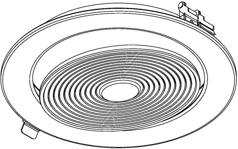
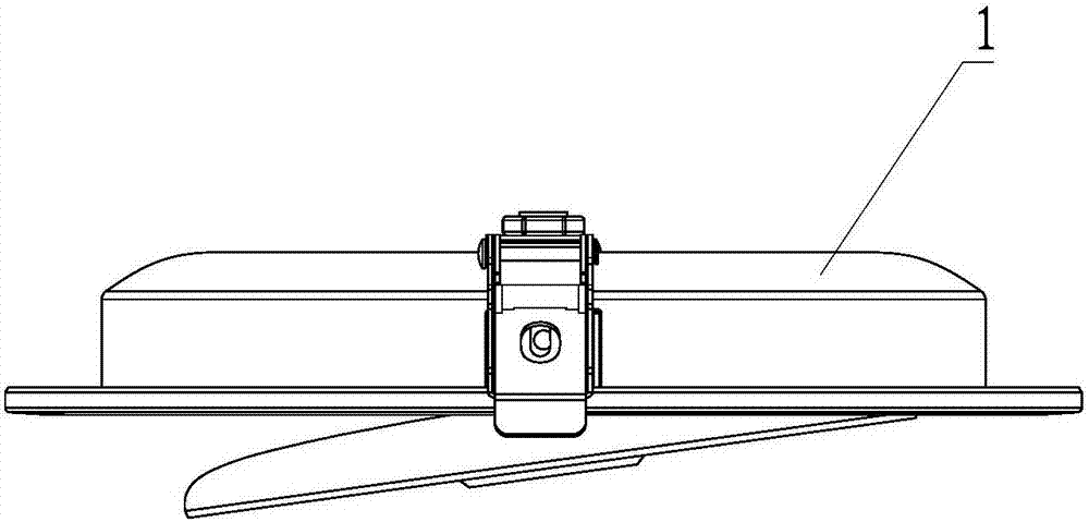
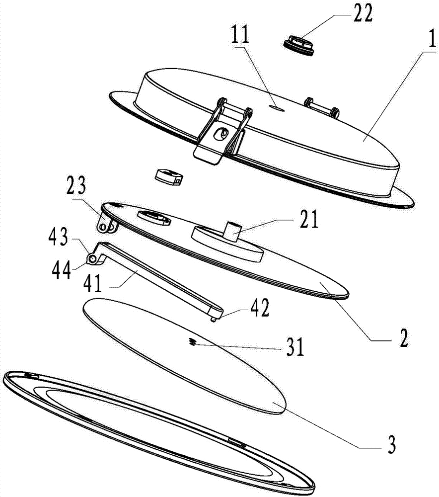
[0031] refer to Figure 1-7 , a rotatable and deflectable downlight structure, comprising: a rear cover 1, a rotating chassis 2, a light emitting module 3 and a deflection bracket 4;

[0032] The rear cover 1 has an accommodating cavity extending axially, the bottom of the accommodating cavity is provided with an opening 11 at the axis; the rotating chassis 2 is coaxially arranged in the accommodating cavity , and its side facing the bottom of the accommodating cavity is provided with a rotating shaft 21; the rotating shaft 21 is fixedly connected with a fixing member 22 after passing through the accommodating opening 11; Axial rotation of cavity;

[0033] The side of the rotating chassis 2 away from the bottom of the accommodating cavity is connected to the yaw bracket 4 in an eccentric position along the axial swing;

[0034] The main body...


PUM


Abstract

The invention provides a down lamp structure capable of rotating and swinging. The down lamp structure comprises a rear cover, a rotary base plate, a light emitting module and a swinging bracket; the rear cover comprises an accommodating chamber extending along the axial direction; the bottom of the accommodating chamber is provided with an abdicating opening at the axis position; the rotary base plate is coaxially arranged inside the accommodating chamber; one surface, facing to the bottom surface of the accommodating chamber, of the rotary base plate is provided with a rotating shaft; the rotating shaft is fixedly connected with a fixing part after passing through the abdicating opening so that the rotary base plate rotates about the axial direction of the accommodating chamber with respect to the accommodating chamber; one surface, far away from the bottom of the accommodating chamber, of the rotary base plate is connected with the swinging bracket in a swinging manner at an eccentric position and along the axial direction; the main body of the swinging bracket is arranged along the radial direction of the rotary base plate; the position coaxial to the rotating shaft is provided with a connecting part linked with the light emitting module; and the light emitting module rotates with the rotary base plate along the radial direction by virtue of the connecting part and also swings with the swinging bracket along the axial direction by virtue of the connecting part.

Description

technical field [0001] The invention relates to a lighting device, in particular to a downlight. Background technique [0002] Downlights play an important role in modern home decoration design. Compared with chandeliers, downlights are hidden and concealed, which can better integrate with home decoration. Moreover, the brightness of the downlight is concentrated, which is especially suitable for local lighting, highlighting the illuminated subject, and can create a completely different light intensity distribution from the chandelier in home decoration, especially suitable for highlighting a certain subject, so it is loved by people. However, the light output angle of traditional downlights cannot be adjusted, and the installation of lamps is earlier than soft decoration. Therefore, it often happens that the installation position of the lamp is not in the same position as the object that needs to be highlighted in the soft decoration in the future. At this time, the objec...

Claims


Application Information

Patent Timeline
IPC IPC(8): F21S8/02F21V21/30F21V13/02F21Y115/10
CPCF21S8/026F21V13/02F21V21/30F21Y2115/10
Inventor 曾天赐叶晓军陈亚涛
Owner LEEDARSON LIGHTING FIXTURES CO LTD
Learn More