Precision Compensation Method for Ball Nose Radius of Contact Measuring Stylus
A technology of contact measurement and precision compensation, applied in the direction of measuring devices, instruments, etc., to improve detection accuracy and reliability, high efficiency, and solve the effect of ball head radius compensation
Inactive Publication Date: 2019-07-12
SICHUAN UNIV
View PDF5 Cites 0 Cited by
- Summary
- Abstract
- Description
- Claims
- Application Information
AI Technical Summary
Problems solved by technology
[0006] In view of the above-mentioned deficiencies in the prior art, the present invention proposes a precision compensation method for the ball head radius of the stylus in contact measurement, which is used to solve the problems existing in the compensation of the ball head radius of the stylus in the existing contact measurement
Method used
View moreImage
Smart ImageViewing Examples


Examples
Embodiment approach
[0029] In summary, a typical implementation of the present invention is as follows:
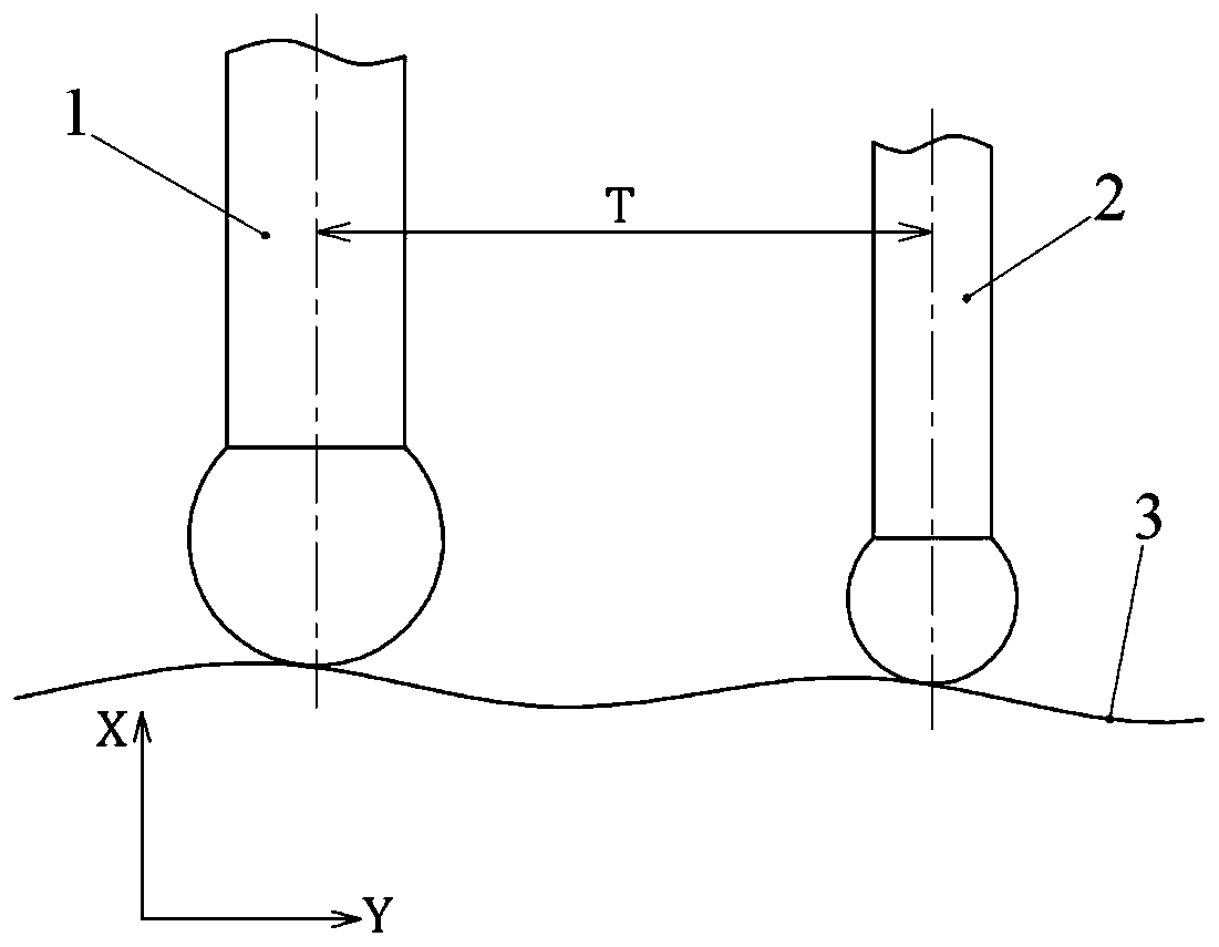
[0030] Arrange the positions of stylus 1(1) and stylus 2(2) reasonably according to the testing requirements.
Login to View More PUM
 Abstract
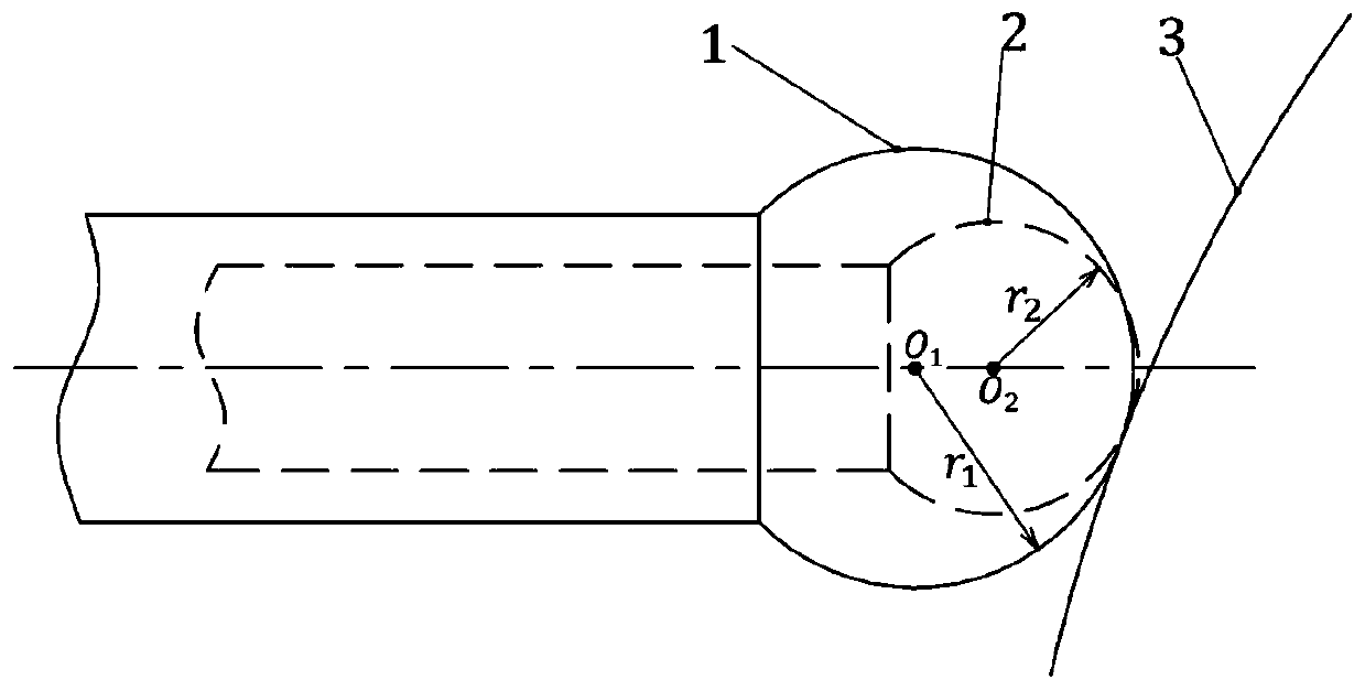
The invention discloses a method for precise compensation of probe ball head radiuses in contact measurement. The method for precise compensation of the probe ball head radiuses in contact measurement comprises the following steps of measuring a same target point of a to-be-detected surface by using two probes with unequal ball head radiuses; carrying out first detection on the target point by using the probe 1 to obtain a detected value of the probe 1; carrying out second detection on the target point by using the probe 2 to obtain a detected value of the probe 2; and calculating a position value of the target point on the basis of the detected values of the probe 1 and the probe 2 on the same target point and the ball head radiuses of the two probes. Contact measurement is carried out on the same target point by adopting the two probes with the unequal ball head radiuses, and the detected values of the target value are finally obtained through direct calculation of the measuring value of the two probes, so that the problem of ball head radius compensation during detection of a complicated spatial curved surface of an unknown parameter can be effectively solved and the detection accuracy and reliability of the contact measurement method are greatly improved.
Description
technical field [0001] The invention belongs to the technical field of contact detection of complex free space curved surfaces, in particular to a method for precise compensation of the ball head radius of a contact measurement probe. Background technique [0002] Contact measurement methods are widely used in object surface detection. For example, in the linear displacement sensor, the retractable stylus is used to detect the target position; in the three-coordinate measuring machine, the complex curved surface of the object is detected by the tactile stylus. However, there is an inherent problem with inspection with tactile styli, which is the compensation of stylus ball tip radius. Since the detection end of the stylus is a ball head, the measurement system can only record the center position of the ball head, and the actual position on the detection surface can only be obtained after radius compensation. Since the normal vector of the detection point on the complex sur...
Claims
Login to View More Application Information
Patent Timeline
 Patent Type & Authority Patents(China)
IPC IPC(8): G01B21/10
CPCG01B21/10
Inventor 陈珂蒋伟
Owner SICHUAN UNIV
Features
- R&D
- Intellectual Property
- Life Sciences
- Materials
- Tech Scout
- Unparalleled Data Quality
- Higher Quality Content
- 60% Fewer Hallucinations
Learn More Browse by: Latest US Patents, China's latest patents, Technical Efficacy Thesaurus, Application Domain, Technology Topic, Popular Technical Reports.
© 2025 PatSnap. All rights reserved.Legal|Privacy policy|Modern Slavery Act Transparency Statement|Sitemap|About US| Contact US: help@patsnap.com