Display panel assembly and a terminal

A display panel and component technology, applied in the field of display panel components and terminals

Inactive Publication Date: 2017-10-10
NUBIA TECHNOLOGY CO LTD
View PDF5 Cites 22 Cited by
  • Summary
  • Abstract
  • Description
  • Claims
  • Application Information

AI Technical Summary

Problems solved by technology

[0003] The technical problem to be solved by the present invention is: the pixel density of the existing display screen is uniform. When the optical refraction of the arc edge is used to realize the borderless, due to the refraction imaging, the image displayed on the display screen corresponding to the arc edge will be enlarged, resulting in the display The problem that the overall imaging ratio of the screen is inconsistent affects the user's visual experience

Method used


Image

  • Display panel assembly and a terminal
  • Display panel assembly and a terminal
  • Display panel assembly and a terminal

Examples


no. 1 example

[0052] Existing mobile terminal display screens have different resolutions, such as 720P, 1080P, 2K, and 4K. The difference between them is that the pixel density is different, but for a mobile terminal or a display screen, its pixel density is uniform. Therefore, when using the optical refraction of the arc edge to hide the black edge area of ​​the display screen, due to refraction imaging, the arc edge area will enlarge part of the image displayed on the display screen, which will cause the imaging ratio of the entire display screen to be inconsistent and affect For user experience, in order to solve the above problems, this embodiment provides a display panel assembly.

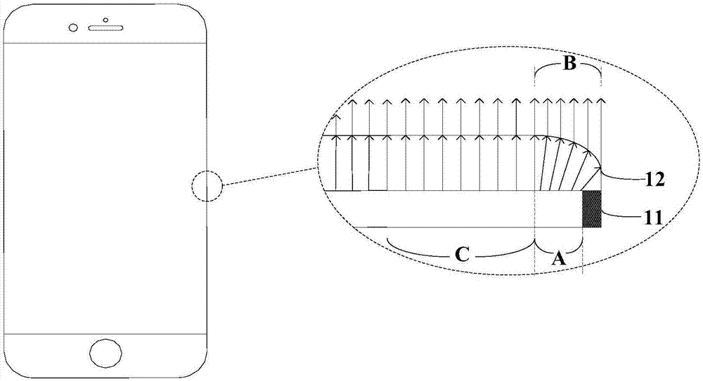
[0053] See image 3As shown, the display panel assembly provided in this embodiment includes a display screen 11 and a transparent cover plate 12 arranged on the display screen 11. The transparent cover plate includes a main see-through area 121 and at least one sloped see-through area located at the edge o...

no. 2 example

[0064] In order to better understand the present invention, this embodiment provides a more specific display panel assembly on the basis of the first embodiment. For details, please refer to Figure 9 shown.

[0065] The display panel assembly provided in this embodiment includes a display screen 11 and a transparent cover plate 12 arranged on the display screen 11. The transparent cover plate 12 includes a main see-through area 121 and at least one slope see-through area located on the edge of the main see-through area 121 122. It can be understood that any one side, two sides, three sides, or four sides of the edge of the main see-through area 121 can be respectively provided with a slope see-through area 122, wherein the slope see-through area 122 in this embodiment is used Since the surface that refracts and transmits light is an arc surface, it should be understood that the arc surface in this embodiment can be Figure 9 In addition to the convex arc surface shown, it ma...

no. 3 example

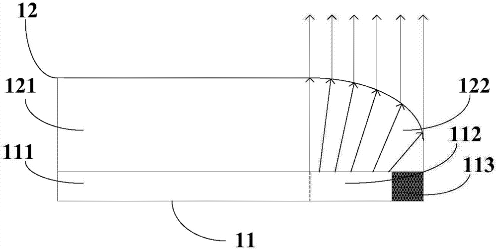
[0068] This embodiment provides a display panel assembly on the basis of the first embodiment, please refer to Figure 10 As shown, the display panel assembly provided in this embodiment includes a display screen 11 and a transparent cover plate 12 arranged on the display screen 11. The transparent cover plate 12 includes a main perspective area 121 and a slope perspective area located at the edge of the main perspective area 121. area 122, wherein, the surface of the slope perspective area 122 in this embodiment is used to refract the transmitted light is a slope, and the display screen 11 in this embodiment includes corresponding to the above-mentioned main perspective area 121 and the slope see-through area 122 respectively. The first display area 111 and the second display area 112. The display screen 11 in this embodiment also includes a black border area 113 that cannot display images corresponding to the slope perspective area 122. The black border area 113 is located in...


PUM


Abstract

The invention discloses a display panel assembly and a terminal. The display panel assembly comprises a display screen and a transparent cover plate arranged on the display screen, the transparent cover plate comprises a main perspective area and at least one slope perspective area located on the edge of the main perspective area, the display screen comprises a first display area and a second display area which correspond to the main perspective area and the slope perspective area respectively, an image displayed in the second display area covers the slope perspective area through refraction, and the average pixel density of the second display area is larger than the average pixel density of the first display area, so that the image displayed in at least one part of the second display area is smaller than an image displayed in the first display area; the image displayed in the second display area can be magnified by means of the slope perspective area so that the proportion of the image displayed in the corresponding area, with the pixel density larger than that of the first display area, in the second display area is closer to the proportion of the image displayed in the first display area, and accordingly the uniform display of the images can be roughly achieved for the whole display screen.

Description

technical field [0001] The present invention relates to the field of display technology, and more specifically, to a display panel assembly and a terminal. Background technique [0002] Recently, various display devices that display images, such as liquid crystal display devices, plasma display panels, and organic light-emitting diode display devices, have emerged, and these display devices have been used in various products such as notebooks, televisions, and tablet personal computers, especially When these display devices are applied in the field of mobile terminals, in order to obtain a better visual experience and a larger screen-to-body ratio, the frame of the front display area of ​​the mobile terminal has become narrower and narrower, and even the left and right borderless technology has appeared. Due to technological limitations of the screen, there is usually a black border area around the display pixel that does not have a display function. The essence of the exist...

Claims


Application Information

Patent Timeline
IPC IPC(8): G09F9/35G09F9/33
CPCG09F9/35G09F9/33
Inventor 彭翊
Owner NUBIA TECHNOLOGY CO LTD
Why Eureka
Try Eureka