
Optical coupling amplifier circuit

An amplifier circuit and preamplifier technology, applied in the field of optoelectronics, to achieve the effect of high current transfer ratio and good linear transmission

Inactive Publication Date: 2017-10-10
SUZHOU HUALAI PHOTOELECTRIC INSTR
View PDF0 Cites 1 Cited by
  • Summary
  • Abstract
  • Description
  • Claims
  • Application Information

AI Technical Summary

Problems solved by technology

[0002] There are many existing amplification circuits, but each has its own advantages and disadvantages. In order to perform current amplification, linear transmission, signal passband, etc. are often sacrificed.

Method used


Image

  • Optical coupling amplifier circuit

Examples


Embodiment Construction

[0014] The present invention will be further described below in conjunction with the accompanying drawings. The following examples are only used to illustrate the technical solution of the present invention more clearly, but not to limit the protection scope of the present invention.

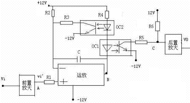
[0015] Such as figure 1 As shown, the optocoupler amplifier circuit of the present invention includes a preamplifier, an operational amplifier, a postamplifier, a first optocoupler OC1 and a second optocoupler OC2.

[0016] The input signal Vi is input to the non-inverting input terminal of the operational amplifier after passing through the preamplifier, and the feedback capacitor C is connected between the output terminal of the operational amplifier and the inverting input terminal, and the output terminal of the operational amplifier is connected to the diode of the first optocoupler OC1 at the same time Cathode, the diode anode of the first optocoupler OC1 is connected to the diode cathode...


PUM


Abstract

The invention discloses an optocoupler amplifier circuit, comprising a preamplifier, an operational amplifier, a post amplifier, a first optocoupler OC1 and a second optocoupler OC2; the input signal Vi enters the operational amplifier through the preamplifier, and is amplified by the operational amplifier The final output signal passes through the first optocoupler OC1 and the second optocoupler OC2 to output a current signal, and the current signal passes through five resistors to output a voltage signal, and finally enters the post-amplifier to amplify and output the signal Vo. The optocoupler amplifier circuit of the invention has high current transfer ratio and good linear transmission performance.

Description

technical field [0001] The invention relates to an optocoupler amplifier circuit, which belongs to the field of optoelectronic technology. Background technique [0002] There are many existing amplification circuits, but each has its own advantages and disadvantages. In order to perform current amplification, linear transmission and signal passband are often sacrificed. Contents of the invention [0003] The technical problem to be solved by the invention is to overcome the defects of the prior art and provide an optocoupler amplifier circuit with high current transfer ratio and good linear transmission. [0004] In order to solve the above technical problems, the present invention provides an optocoupler amplifier circuit, which is characterized in that it includes a preamplifier, an operational amplifier, a postamplifier, a first optocoupler OC1 and a second optocoupler OC2; [0005] The input signal Vi enters the op amp through the preamplifier, and the output signal a...

Claims


Application Information

Patent Timeline
Patent Type & Authority Applications(China)
IPC IPC(8): H03F17/00H03F3/68H03F1/34H03F1/42
CPCH03F17/00H03F1/34H03F1/42H03F3/68
Inventor 薛文英
Owner SUZHOU HUALAI PHOTOELECTRIC INSTR
Learn More