High-pressure hydrogen gas refrigerating device of hydrogen internal combustion engine vehicle

A technology of high-pressure hydrogen and refrigeration equipment, which is applied in the direction of household refrigeration equipment, refrigerators, refrigeration components, etc., and can solve the problems of large condenser and evaporator equipment, large space occupation, and engine consumption

Inactive Publication Date: 2017-10-13
BEIJING INSTITUTE OF TECHNOLOGYGY
View PDF8 Cites 3 Cited by
  • Summary
  • Abstract
  • Description
  • Claims
  • Application Information

AI Technical Summary

Problems solved by technology

In the traditional vapor compression refrigeration cycle, not only the compressor needs to consume the mechanical work of the engine, which affects the operation of the vehicle, but also the large equipment such as the condenser and evaporator takes up a lot of space

Method used


Image

  • High-pressure hydrogen gas refrigerating device of hydrogen internal combustion engine vehicle
  • High-pressure hydrogen gas refrigerating device of hydrogen internal combustion engine vehicle
  • High-pressure hydrogen gas refrigerating device of hydrogen internal combustion engine vehicle

Examples


Embodiment example 1

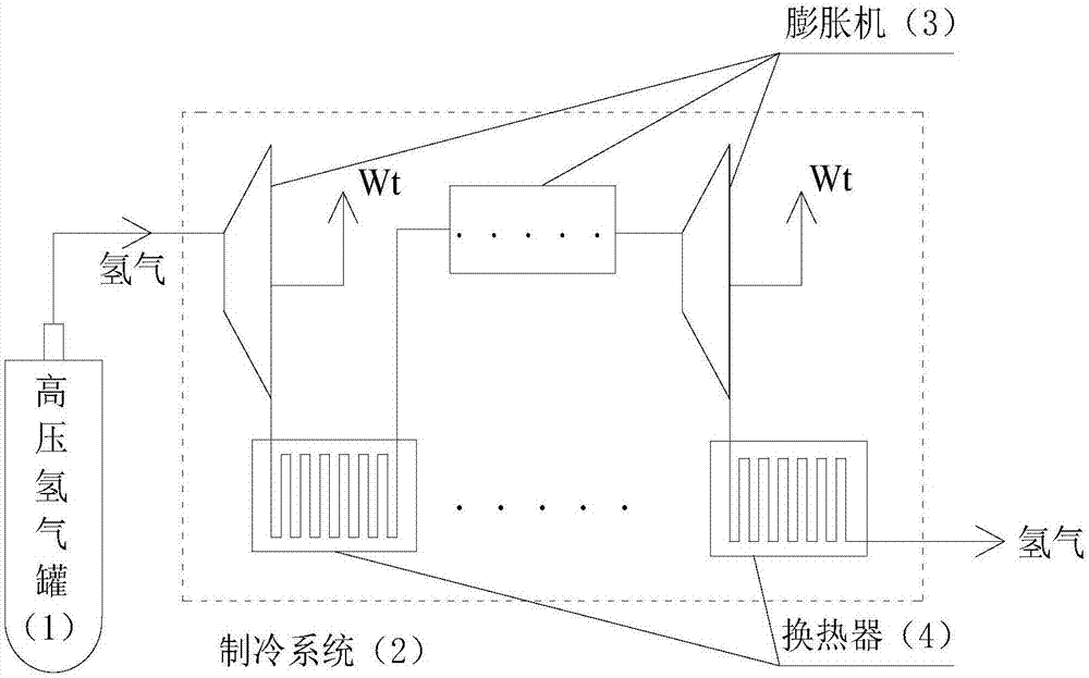
[0018] Such as image 3 As shown, a high-pressure hydrogen refrigeration device for a hydrogen internal combustion engine vehicle includes: a high-pressure hydrogen tank (1), a refrigeration system (2), and the refrigeration system (2) includes an expander (3) and a heat exchanger (4). This case uses a one-stage expansion system. In refrigeration mode: high-pressure hydrogen flows out of the high-pressure hydrogen tank (1), first passes through the piston expander (3) to reduce temperature and pressure, and outputs power to the outside, and then flows into the air-cooled heat exchanger ( 4) Release cold energy to cool down the interior of the car.

Embodiment example 2

[0020] Such as Figure 4 As shown, a high-pressure hydrogen refrigeration device for a hydrogen internal combustion engine vehicle includes: a high-pressure hydrogen tank (1), a refrigeration system (2), and the refrigeration system (2) includes a screw expander (3) and a water-cooled heat exchanger ( 4), refrigerator (7) in the car. This case adopts a three-stage expansion system. High-pressure hydrogen flows out of the high-pressure hydrogen tank (1) and flows into the expansion systems of each stage in turn; in the expansion system of each stage, the hydrogen flows into the first-stage scroll expander (3) to cool down and reduce pressure. Output work, and then flow into the first-stage water-cooled heat exchanger (4) to absorb heat; then flow into the second-stage scroll expander (3) to expand and reduce pressure, do work externally, and flow into the second-stage water-cooled heat exchanger (4) to absorb heat Finally, it flows into the three-stage scroll expander (3) to e...

Embodiment example 3

[0022] Such as Figure 5 As shown, the gas supply system for a hydrogen internal combustion engine vehicle includes: a high-pressure hydrogen tank (1), a refrigeration system (2), an expander (3), a heat exchanger (4), a condenser (8), and an air turbocharger ( 9), nozzle (10), internal combustion engine (11), water tank (12). Hydrogen gas supply pipeline: hydrogen flows out of the high-pressure hydrogen tank (1) and flows through the expansion system at all levels. In this case, the two-stage expansion system is used; in the expansion system at all levels, the hydrogen first flows into the one-stage radial flow expander (3) for expansion Reduce the pressure, do work outside, flow into the first-stage air-cooled heat exchanger (4) to release the cooling capacity, and cool down the inside of the car; then flow into the second-stage radial flow expander (3) to expand and reduce pressure, do work outside, and flow into the second-stage The air-cooled heat exchanger (4) releases ...


PUM


Abstract

The invention provides a high-pressure hydrogen gas refrigerating device of a hydrogen internal combustion engine vehicle. The high-pressure hydrogen gas refrigerating device comprises a high-pressure hydrogen gas tank (1) and a refrigerating system (2), wherein the refrigerating system (2) comprises one or multiple stages of expanding systems; and the expanding system at each stage comprises an expander (3) and a heat exchanger (4). High-pressure hydrogen gas flows out from the high-pressure hydrogen gas tank (1) and sequentially flows into the expanding system at each stage. In the expanding system at each stage, high-pressure hydrogen gas is cooled and decompressed by the expander (3) to output work outsides, and then enters the heat exchanger (4); when refrigerating is needed in the vehicle, cooling capacity is provided into the vehicle; and when refrigerating is not needed in the vehicle, heat exchange is performed with the environment or engine cooling circulating water. The refrigerating system (2) is used for recycling pressure energy in the high-pressure hydrogen gas tank, and also provides cooling capacity to a control cabinet, so that an energy utilization rate is increased.

Description

technical field [0001] The invention relates to a refrigeration device for a hydrogen energy vehicle, in particular to a high-pressure hydrogen refrigeration device. Background technique [0002] Such as figure 1 , 2 As shown, the traditional hydrogen internal combustion engine vehicle uses a vapor compression refrigeration cycle. Refrigerant is compressed by the compressor (5), increases the pressure from state point 1 to state point 2, then flows through the condenser (6) to release heat, and cools down from state point 2 to state point 4 at equal pressure, and passes through the throttle valve ( 3) Expansion, depressurization and temperature reduction from state point 4 to state point 5, and finally flow into the evaporator (13) to absorb heat in the car to complete refrigeration. In the traditional vapor compression refrigeration cycle, not only the compressor needs to consume the mechanical work of the engine, which affects the operation of the vehicle, but also the ...

Claims


Application Information

Patent Timeline
Patent Type & Authority Applications(China)
IPC IPC(8): F25B1/00F25B41/06F25D1/00F25D1/02F25B41/30
CPCF25B1/00F25D1/00F25D1/02F25B41/31
Inventor 康慧芳那晓雨孙柏刚卢凌赳
Owner BEIJING INSTITUTE OF TECHNOLOGYGY
Why Eureka
Try Eureka