High pressure hydrogen refrigerating device for hydrogen fuel cell vehicle

A high-pressure hydrogen and fuel cell technology, used in refrigerators, refrigeration and liquefaction, compressors, etc., can solve problems such as affecting vehicle operation, consuming motors, and occupying large space for condensers and evaporators

Pending Publication Date: 2017-08-22
BEIJING INSTITUTE OF TECHNOLOGYGY
View PDF7 Cites 7 Cited by
  • Summary
  • Abstract
  • Description
  • Claims
  • Application Information

AI Technical Summary

Problems solved by technology

In the traditional vapor compression refrigeration cycle, not only the compressor needs to consume the electric power of the motor, which affects the operation of the vehicle, but also the large equipment such as the condenser and evaporator takes up a lot of space

Method used


Image

  • High pressure hydrogen refrigerating device for hydrogen fuel cell vehicle
  • High pressure hydrogen refrigerating device for hydrogen fuel cell vehicle
  • High pressure hydrogen refrigerating device for hydrogen fuel cell vehicle

Examples


Embodiment example 1

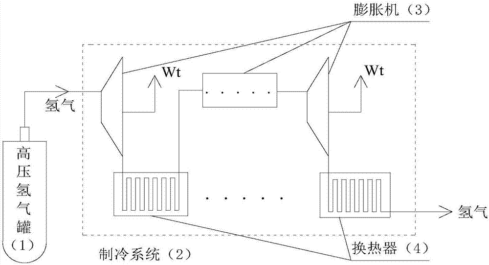
[0018] Such as Figure 4 As shown, a high-pressure hydrogen refrigeration device for a hydrogen fuel cell automobile includes: a high-pressure hydrogen tank (1), a refrigeration system (2), and the refrigeration system (2) includes an expander (3) and a heat exchanger (4). This case uses a one-stage expansion system. In the refrigeration mode: high-pressure hydrogen flows out of the high-pressure hydrogen tank (1), first passes through the piston expander (3) to reduce temperature and pressure, outputs work externally, and then flows into the air-cooled heat exchanger ( 4) Release cold to cool down the car interior.

Embodiment example 2

[0020] Such as Figure 5 As shown, a high-pressure hydrogen refrigeration device for a hydrogen fuel cell automobile includes: a high-pressure hydrogen tank (1), a refrigeration system (2), and the refrigeration system (2) includes a screw expander (3) and a water-cooled heat exchanger (4), the refrigerator in the car (7). This case uses a three-stage expansion system. High-pressure hydrogen flows out of the high-pressure hydrogen tank (1) and flows into the expansion system of each stage in sequence; in the expansion system of each stage, the hydrogen flows into the first-stage scroll expander (3) to reduce temperature and pressure, and Output work, and then flow into the first-stage water-cooled heat exchanger (4) to absorb heat; then flow into the second-stage scroll expander (3) to expand and depressurize, do work externally, and flow into the second-stage water-cooled heat exchanger (4) to absorb heat ; Finally, it flows into the three-stage scroll expander (3) to expand a...

Embodiment example 3

[0022] Such as Image 6 As shown, the hydrogen fuel cell vehicle gas supply system includes: high-pressure hydrogen tank (1), refrigeration system (2), expander (3), heat exchanger (4), condenser (8), hydrogen heater (9) ), hydrogen humidifier (10), water tank (11), water separator (12), air humidifier (13), fuel cell (14), water separator (15), air heater (16), compressor (17). Anode gas supply pipeline: Hydrogen flows out of the high-pressure hydrogen tank (1) and flows into the expansion system of each stage in turn. This case uses a two-stage expansion system; in the expansion system of each stage, the hydrogen flows into the first-stage radial expander (3). It flows into the first-stage air-cooled heat exchanger (4) to release the cold and cools the interior of the car; then flows into the second-stage radial expander (3) to expand and depressurize, perform external work, and then flow into the second Stage air-cooled heat exchanger (4) releases cold energy to cool the i...


PUM


Abstract

The invention provides a high pressure hydrogen refrigerating device for a hydrogen fuel cell vehicle, comprising a high pressure hydrogen tank (1) and a refrigerating system (2), wherein the refrigerating system (2) comprises one stage or multiple stages of expansion systems, and each stage of expansion system comprises an expansion machine (3) and a heat exchanger (4). High pressure hydrogen flows out of the high pressure hydrogen tank (1) and sequentially flows into each stage of expansion system; in each stage of expansion system, the temperature and pressure of high pressure hydrogen are firstly reduced by the expansion machine (3) to output power to the outside, and then high pressure hydrogen enters the heat exchanger (4); when the inside of the vehicle needs to be refrigerated, cold energy is supplied to the inside of the vehicle; and when the inside of the vehicle does not need to be refrigerated, high pressure hydrogen carries out heat exchange with environment or fuel battery cooling circulating water. The pressure energy in the high pressure hydrogen tank is recycled by the refrigerating system (2), and meanwhile, the cold energy is supplied to a cockpit, thereby improving the energy utilization rate.

Description

Technical field [0001] The invention relates to a refrigeration device for hydrogen energy vehicles, in particular to a high-pressure hydrogen refrigeration device. Background technique [0002] Such as figure 2 , 3 As shown, the traditional hydrogen fuel cell vehicle uses a vapor compression refrigeration cycle. The refrigerant is compressed by the compressor (5), boosts the pressure from the state point 1 to the state point 2, and then flows through the condenser (6) to release heat, and drops the temperature at the same pressure from the state point 2 to the state point 4, and passes through the throttle valve ( 3) Expansion, depressurization and temperature reduction from state point 4 to state point 5, and finally flow into the evaporator (18) to absorb heat in the car to complete cooling. In the traditional vapor compression refrigeration cycle, not only the compressor needs to consume the electric power of the motor, which affects the operation of the vehicle, but also th...

Claims


Application Information

Patent Timeline
IPC IPC(8): B60H1/32F25B9/06
CPCF25B9/06B60H1/3227
Inventor 那晓雨康慧芳韩恺郑子阳
Owner BEIJING INSTITUTE OF TECHNOLOGYGY
Why Eureka
Try Eureka