
Display panel, electronic equipment and method for manufacturing display panel

A technology for display panels and manufacturing methods, applied in the fields of nonlinear optics, instruments, optics, etc., capable of solving problems such as the frame width of display panels

Inactive Publication Date: 2017-10-13
TCL CHINA STAR OPTOELECTRONICS TECH CO LTD
View PDF7 Cites 26 Cited by
  • Summary
  • Abstract
  • Description
  • Claims
  • Application Information

AI Technical Summary

Problems solved by technology

In the production of traditional display panels, the border area of ​​the array substrate needs to reserve a binding area for binding the circuit board, resulting in the border of the display panel is usually wider

Method used


Image

  • Display panel, electronic equipment and method for manufacturing display panel
  • Display panel, electronic equipment and method for manufacturing display panel
  • Display panel, electronic equipment and method for manufacturing display panel

Examples


Embodiment Construction

[0034] The technical solutions in the embodiments of the present invention will be described below with reference to the accompanying drawings in the embodiments of the present invention. Obviously, the described embodiments are only some of the embodiments of the present invention, not all of them. Based on the embodiments of the present invention, all other embodiments obtained by persons of ordinary skill in the art without creative efforts fall within the protection scope of the present invention.

[0035] In addition, the following descriptions of the various embodiments refer to the attached drawings to illustrate specific embodiments in which the present invention can be implemented. The directional terms mentioned in the present invention, for example, "upper", "lower", "front", "rear", "left", "right", "inner", "outer", "side", etc., only is to refer to the direction of the attached drawings. Therefore, the direction terms used are for better and more clearly explaini...


PUM


Abstract

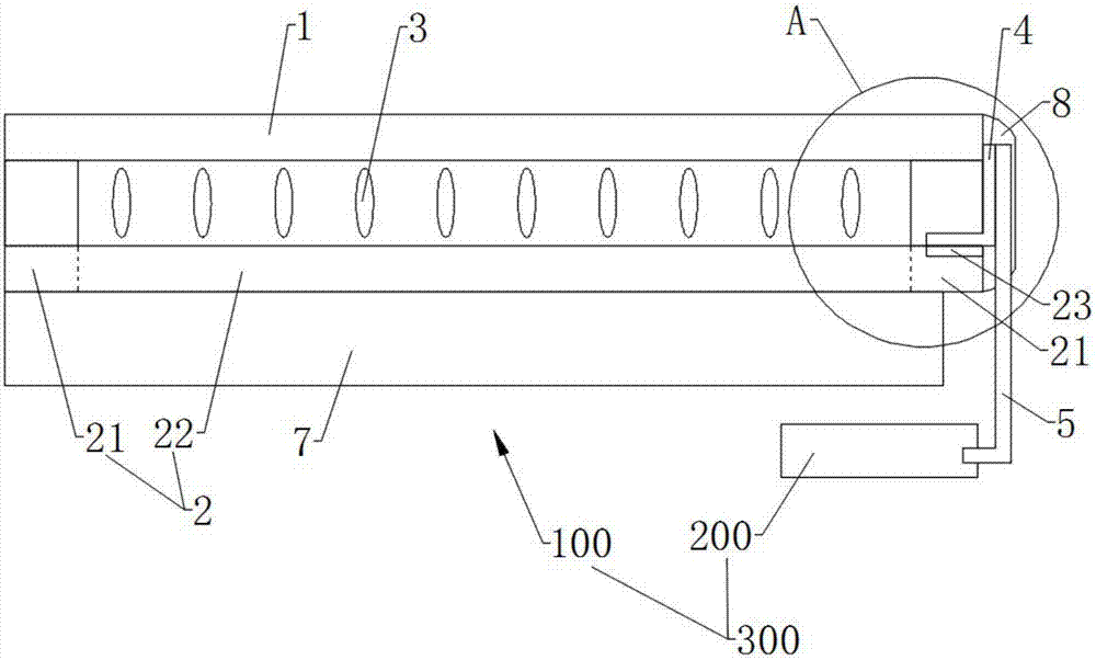
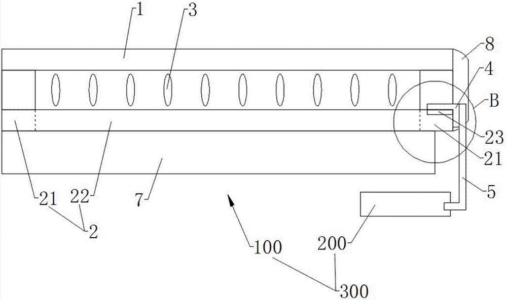
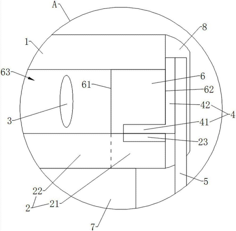
The invention discloses a display panel which comprises color film substrates, array substrates and electrically conductive components. The array substrates are opposite to the color film substrates. The electrically conductive components comprise fixed ends and movable ends, the fixed ends are opposite to the movable ends, are positioned between the array substrates and the color film substrates and are electrically connected with the array substrates, and the movable ends extend out of spaces between the array substrates and the color film substrates and are used for binding circuit boards. The invention further discloses electronic equipment and a method for manufacturing the display panel. The display panel, the electronic equipment and the method have the advantage that the display panel is provided with narrow frames.

Description

technical field [0001] The present invention relates to the technical field of electronic display devices, in particular to a display panel, a display area and a manufacturing method of the display panel. Background technique [0002] As consumers have higher and higher requirements on the appearance of electronic products, display panels with narrow borders are more and more popular, and are used in various electronic devices (such as mobile phones, TVs, splicing screens, etc.). Because in the traditional manufacturing of display panels, the frame area of ​​the array substrate needs to reserve a binding area for binding circuit boards, the frame of the display panel is usually wider. Contents of the invention [0003] The invention provides a display panel with a narrow frame, electronic equipment and a manufacturing method of the display panel. [0004] The embodiment of the present invention adopts following technical scheme: [0005] In one aspect, a display panel is...

Claims


Application Information

Patent Timeline
IPC IPC(8): G02F1/1333G02F1/1345
CPCG02F1/1333G02F1/13452
Inventor 张伟基
Owner TCL CHINA STAR OPTOELECTRONICS TECH CO LTD
Learn More