Lighting unit and display provided with the same

a technology of light source and light source, which is applied in the direction of lighting and heating apparatus, instruments, optical elements, etc., can solve the problems of increasing manufacturing costs, difficult to restrain luminance unevenness, and burdensome assembly, so as to reduce the number of parts, reduce the number of luminance unevenness, and improve the effect of luminance uniformity

Inactive Publication Date: 2012-01-12
HITACHI CONSUMER ELECTRONICS CORP
View PDF5 Cites 23 Cited by
  • Summary
  • Abstract
  • Description
  • Claims
  • Application Information

AI Technical Summary

Benefits of technology

[0016]According to this invention, a lighting unit is realized which is able to control luminance in each of a plurality of block areas and minimize luminance unevenness, that would otherwise be caused by a plurality of discretely arrayed light sources, and which also has a reduced number of parts. A display using the lighting unit of this invention is high in luminance uniformity on the screen and has a slim bezel and a small thickness. Problems, constructions and advantages of this invention other than those described above will become apparent from the following descriptions of embodiments.

Problems solved by technology

This system, however, has problems that because a plurality of light guide plates are required, the number of parts used becomes large and that since a plurality of light guide plates are arrayed and the light sources are put close to the corresponding light guide plates, the assembly becomes burdensome, increasing the manufacturing cost.
However, it has a problem that if the optical efficiency of the light sources is improved in the future and the number of light sources becomes smaller, it will be difficult to restrain luminance unevenness caused by the discrete arrangement of light sources.

Method used


Image

  • Lighting unit and display provided with the same
  • Lighting unit and display provided with the same
  • Lighting unit and display provided with the same

Examples


embodiment 1

(Embodiment 1 of Lighting Unit)

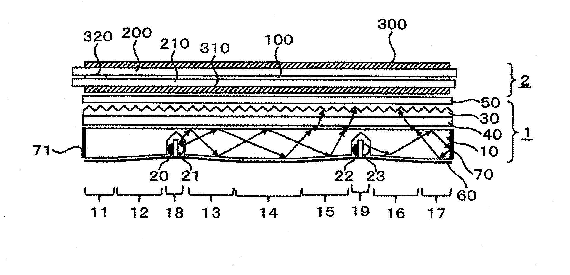
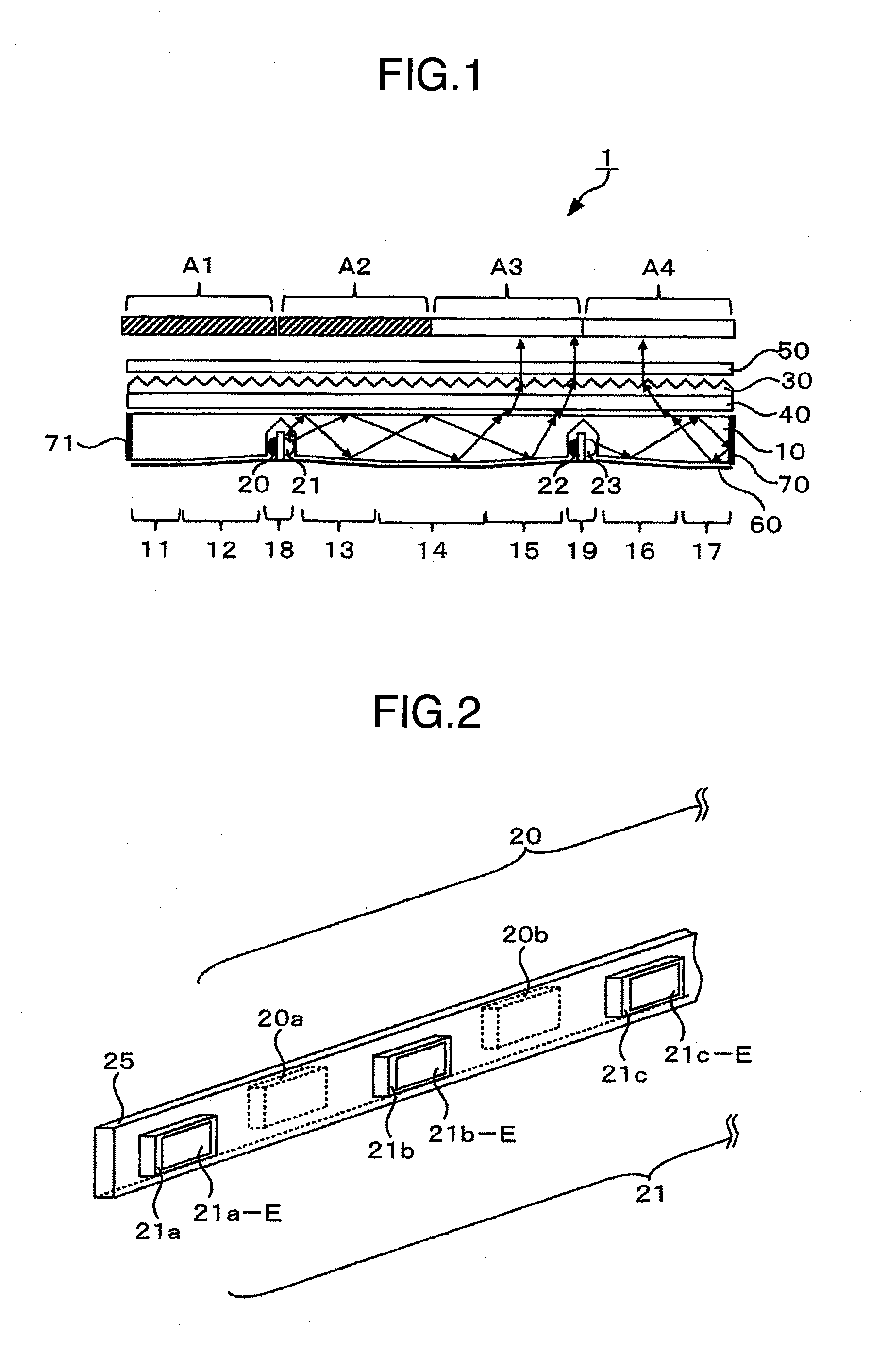
[0036]FIG. 1 is a schematic partial cross-sectioned view showing the structure of the essential portion of an example of the lighting unit of this invention. It is noted that, for ease of explanation, the accompanying drawings are not necessarily represented with correct scales.

[0037]The lighting unit 1 is suitably disposed at the back of a display panel not shown to illuminate the display panel from its back surface. The display panel may be used that displays an image by adjusting the amount of incident light passing therethrough, particularly a long lifed liquid crystal display panel capable of a matrix display.

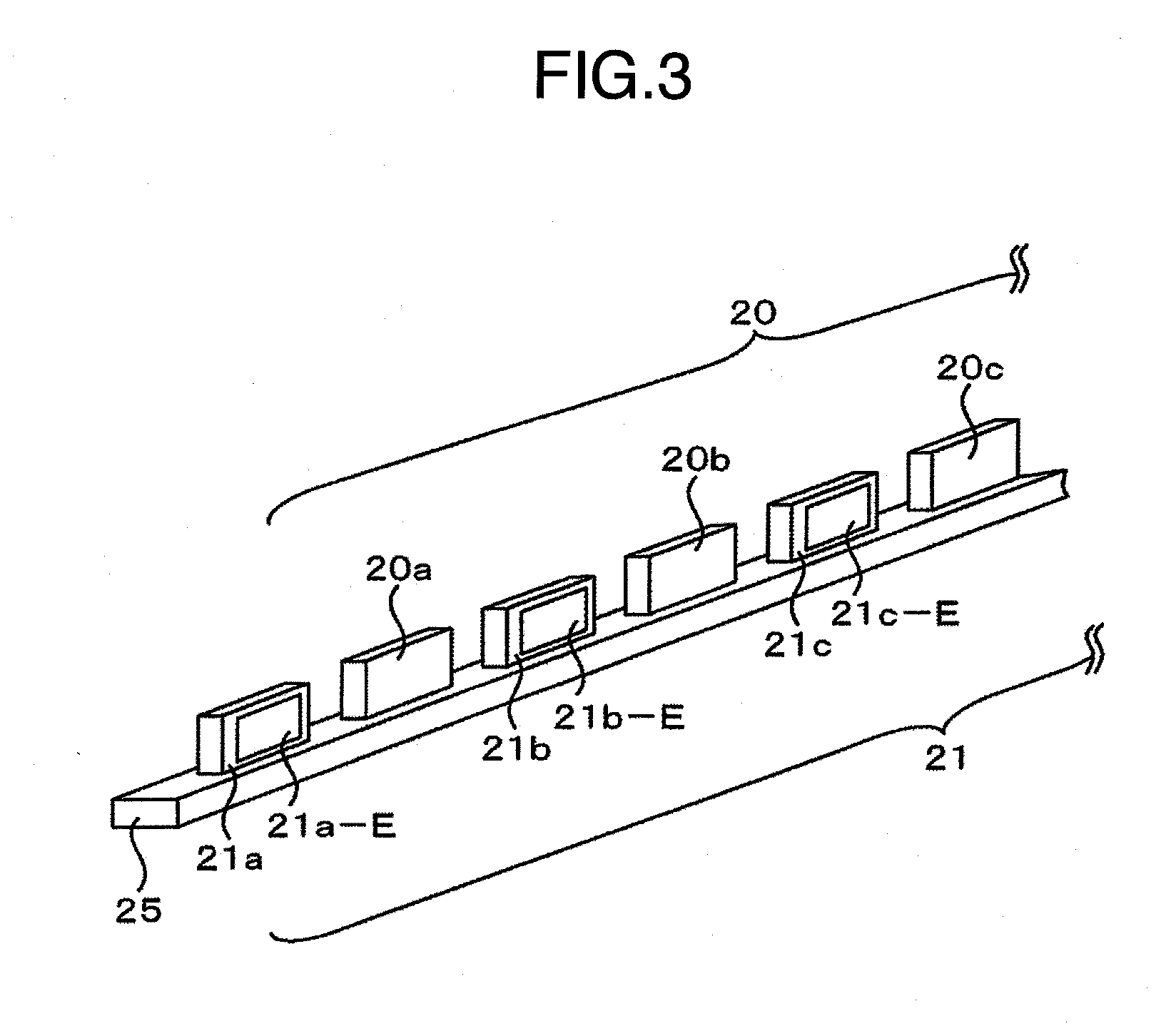
[0038]The lighting unit 1 comprises a light guide plate 10, light source groups 20-23 having a plurality of light sources respectively installed in grooves formed in the light guide plate 10, a light reflector 60 provided at the back surface of the light guide plate 10, light reflectors 70 and 71 provided at the ends of the light guide plate ...


PUM

PropertyMeasurementUnit
surface roughnessaaaaaaaaaa
surface roughness Raaaaaaaaaaa

Abstract

This lighting unit can control luminance in a plurality of block areas independently, and minimize luminance unevenness caused by discretely arrayed light sources, with a reduced number of parts. The lighting unit comprises: a light guide plate having a first and a second grooves formed therein; a first light source group accommodated in the first groove; and a second light source group accommodated in the second groove; the light guide plate having a first light mixing area, a first light emitting area and a second light mixing area; in the first light mixing area, the thickness of the light guide plate progressively increasing away from the first light source group; in the second light mixing area, the thickness of the light guide plate progressively increasing away from the second light source group; and in the first light emitting area, the light guide plate being flat-plate-like.

Description

INCORPORATION BY REFERENCE[0001]The present application claims priority from Japanese application JP2010-156304 filed on Jul. 9, 2010, the content of which is hereby incorporated by reference into this application.BACKGROUND OF THE INVENTION[0002]The present invention relates to a lighting unit and a display having the same.[0003]Displays are media used to visually convey information to humans and play important roles today for humans and the highly sophisticated information society. Displays are classified largely into light emitting type displays, such as CRTs (cathode ray tubes) and PDPs (plasma display panels), and non-light emitting type displays, such as LCDs (liquid crystal displays), ECDs (electrochromic displays) and EPIDs (electrophoretic image displays).[0004]The non-light emitting type displays form an image by adjusting the quantity of light transmission (or light reflection). Of this type of displays, the liquid crystal display in particular has achieved remarkable per...

Claims


Application Information

Patent Timeline
Patent Type & Authority Applications(United States)
IPC IPC(8): G02F1/13357
CPCG02B6/0021G02B6/0038G02B6/0073G02B6/0053G02B6/0068G02B6/0046
Inventor ADACHI, MASAYATSUMURA, MAKOTO
Owner HITACHI CONSUMER ELECTRONICS CORP
Why Eureka
Try Eureka