Light guide plate, method of manufacturing light guide plate and backlight with the light guide plate

a technology of light guide plate and light guide plate, which is applied in the field of backlight units, can solve the problems of large-sized injection molding machine, increased mold cost, and uneven luminance (brightness) of light exit surface, and achieve the effect of reducing the thickness of light guide plate and minimizing the unevenness of light exit surfa

Active Publication Date: 2009-06-09
CITIZEN ELECTRONICS CO LTD
View PDF13 Cites 34 Cited by
  • Summary
  • Abstract
  • Description
  • Claims
  • Application Information

AI Technical Summary

Benefits of technology

[0015]This edge-light type light guide plate also offers advantageous effects similar to those of the above-described edge-light type light guide plate.
[0016]Specifically, the depths and pitches of the elongated concave surfaces may gradually increase with the concave surfaces being situated farther away from the light entrance plane.
[0017]With this arrangement, even if the quantity of light guided closer to the inner part away from the light source in the light guide plate decreases, the light can exit the light exit surface of the light guide plate efficiently, and luminance unevenness on the light exit surface can be minimized.
[0018]The edge-light type light guide plate may be made of a synthetic resin sheet. In this case, the convex and concave surfaces may be press-formed. Thus, the thickness of the light guide plate can be reduced considerably in comparison to the conventional light guide plates.
[0019]Specifically, the convex and concave surfaces may be formed by hot pressing.
[0020]In another specific example, the edge-light type light guide plate may have a resin sheet and UV (ultraviolet) curing resin coating layers provided on both surfaces of the resin sheet to form the first and second surfaces, and the convex and concave surfaces may be press-formed on the UV curing resin coating layers.

Problems solved by technology

The use of a large-sized injection molding machine increases installation cost.
Manufacture of light guide plates of different thickness needs a plurality of injection molds to be prepared therefor, resulting in an increase in mold cost.
The light guide plate provided with sawtooth-shaped prisms as reflecting means, which is disclosed in Japanese Patent Application Publication No. 2003-262735, enables light to be effectively guided toward the inner part of the light guide plate but suffers from the problem that directivity is imparted to light reflected by the prisms 12b, which is likely to cause luminance (brightness) unevenness.

Method used


Image

  • Light guide plate, method of manufacturing light guide plate and backlight with the light guide plate
  • Light guide plate, method of manufacturing light guide plate and backlight with the light guide plate
  • Light guide plate, method of manufacturing light guide plate and backlight with the light guide plate

Examples


Embodiment Construction

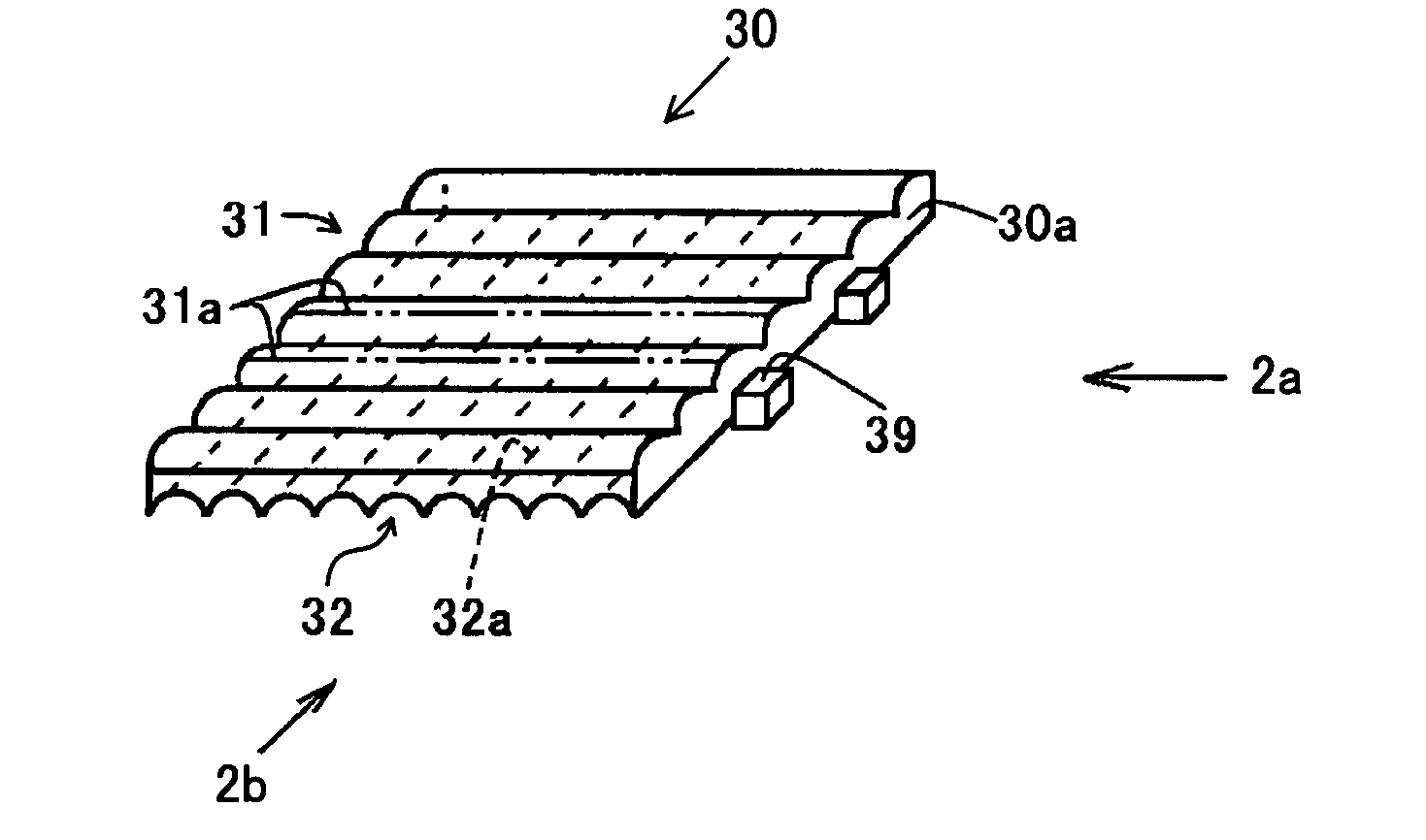
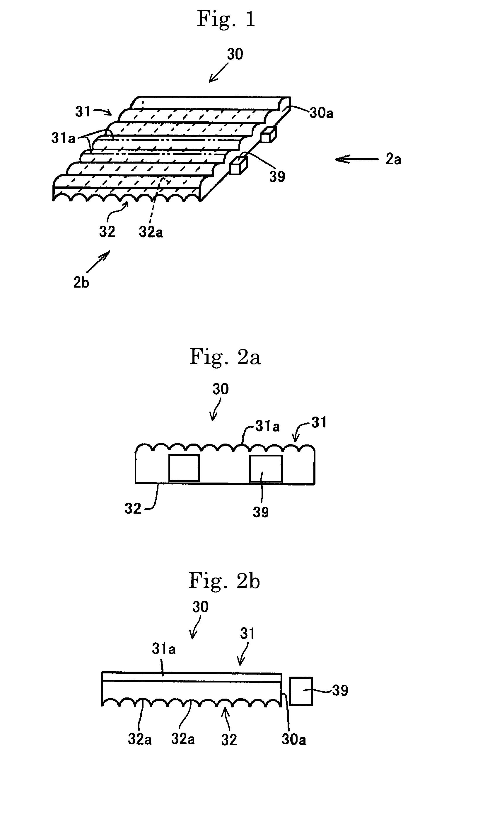
[0065]FIGS. 1 to 2b show an edge-light type rectangular light guide plate 30 according to the present invention.

[0066]The light guide plate 30 has a first surface (upper surface as viewed in the figures) 31, a second surface (lower surface) 32 opposed to the first surface 31, and four side edge surfaces extending between the peripheral edges of the first and second surfaces 31 and 32. One of the side edge surfaces is defined as a light entrance plane 30a. The first surface 31 has a series of elongated convex surfaces 31a extending parallel to each other. The second surface 32 has a series of elongated concave surfaces 32a extending in a direction perpendicularly intersecting the convex surfaces 31a on the first surface 31. The light entrance plane 30a extends in a direction perpendicularly intersecting the elongated convex surfaces 31a. The convex surfaces 31a and concave surfaces 32a have arcuate cross-sections, respectively.

[0067]A light source 39 is set at a position adjacent to ...


PUM


Abstract

An edge-light type light guide plate 30 is provided and has a first surface 31 and a second surface 32 that are opposed to each other, and a peripheral edge surface extending between the peripheral edges of the first and second surfaces. A part of the peripheral edge surface is defined as a light entrance plane 30a. The first surface 31 has a series of parallel elongated convex surfaces 31a that have an arcuate cross-section and extend in a direction substantially perpendicularly intersecting the light entrance plane 30a. The second surface 32 has a series of parallel elongated concave surfaces 32a that have an arcuate cross-section and extend in a direction substantially perpendicularly intersecting the elongated convex surfaces 31a on the first surface.

Description

[0001]This application claims priority under 35 U.S.C. § 119 to Japanese Patent application No. JP2006-113428 filed on Apr. 17, 2006 and No. 2006-224603 filed Aug. 21, 2006, the entire contents of which are hereby incorporated by reference.TECHNICAL FIELD[0002]The present invention relates to backlight units for use in display devices such as liquid crystal display devices. More particularly, the present invention relates to a light guide plate used in an edge-light type lighting device and also relates to a backlight unit using the same.RELATED PRIOR ART[0003]Liquid crystal display devices have been widely used in personal computers, liquid crystal display television systems, electronic organizers, cellular phones, and other terminal display devices. A backlight unit is provided at the lower side of a liquid crystal display panel of such a liquid crystal display device to make the displayed image appear bright and sharp. The backlight unit often uses an edge-light type light guide ...

Claims


Application Information

Patent Timeline
Patent Type & Authority Patents(United States)
IPC IPC(8): F21V7/04
CPCG02B3/0031G02B3/005G02B3/0068G02B6/0038G02B6/0065G02B3/0006G02F1/133615
Inventor SHIMURA, TAKASHI
Owner CITIZEN ELECTRONICS CO LTD
Why Eureka
Try Eureka