
Rapid petroleum filter device for collecting petroleum

A rapid filtration and petroleum technology, which is applied in the direction of filtration separation, mobile filter element filter, separation method, etc., can solve the problem of petroleum waste and achieve the effect of reducing resource waste

Inactive Publication Date: 2017-10-17
沈晓兰
View PDF6 Cites 12 Cited by
  • Summary
  • Abstract
  • Description
  • Claims
  • Application Information

AI Technical Summary

Problems solved by technology

[0006] In order to overcome the shortcomings of inconvenient operation, oil waste and economic loss in the current oil filtration process, the technical problem to be solved by the present invention is to provide a filter that is easy to operate, not easy to cause oil waste, and reduces economic loss. Oil quick filter equipment for oil collection

Method used


Image

  • Rapid petroleum filter device for collecting petroleum
  • Rapid petroleum filter device for collecting petroleum
  • Rapid petroleum filter device for collecting petroleum

Examples


Embodiment 1

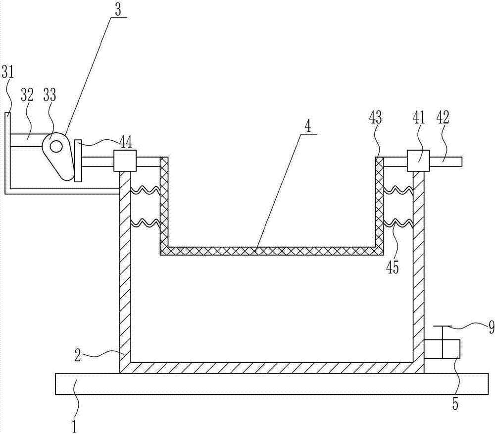
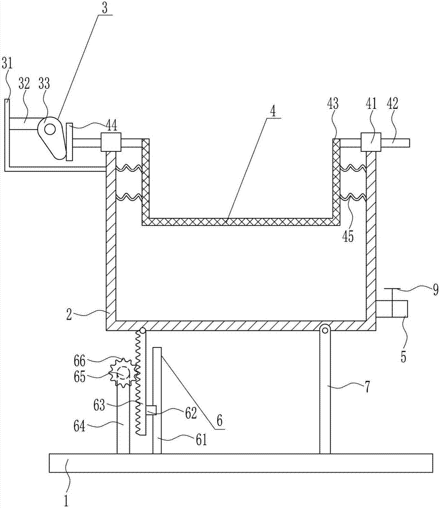
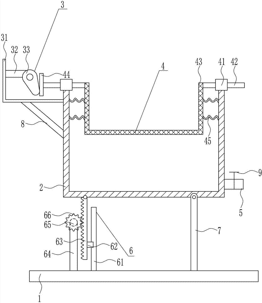
[0027] A kind of quick oil filter equipment for oil collection, such as Figure 1-3 As shown, it includes a bottom plate 1, a frame body 2, a driving device 3, a filter device 4, an oil outlet pipe 5 and a valve 9, a frame body 2 is arranged on the top of the bottom plate 1, a driving device 3 is arranged on the upper left side of the frame body 2, and the frame The upper part of the body 2 is provided with a filter device 4 , the bottom of the right side of the frame body 2 is connected with an oil outlet pipe 5 , and a valve 9 is connected to the oil outlet pipe 5 , and the oil outlet pipe 5 communicates with the inside of the frame body 2 .

Embodiment 2

[0029] A kind of quick oil filter equipment for oil collection, such as Figure 1-3 As shown, it includes a bottom plate 1, a frame body 2, a driving device 3, a filter device 4, an oil outlet pipe 5 and a valve 9, a frame body 2 is arranged on the top of the bottom plate 1, a driving device 3 is arranged on the upper left side of the frame body 2, and the frame The upper part of the body 2 is provided with a filter device 4 , the bottom of the right side of the frame body 2 is connected with an oil outlet pipe 5 , and a valve 9 is connected to the oil outlet pipe 5 , and the oil outlet pipe 5 communicates with the inside of the frame body 2 .

[0030] The driving device 3 includes a fixed plate 31, a mounting plate 32 and an electric cam 33. The upper part of the left side of the frame body 2 is connected with the fixed plate 31 by bolts. The fixed plate 31 is L-shaped, and the left side of the fixed plate 31 passes through the The mode of bolt connection is horizontally conn...

Embodiment 3

[0032] A kind of quick oil filter equipment for oil collection, such as Figure 1-3 As shown, it includes a bottom plate 1, a frame body 2, a driving device 3, a filter device 4, an oil outlet pipe 5 and a valve 9, a frame body 2 is arranged on the top of the bottom plate 1, a driving device 3 is arranged on the upper left side of the frame body 2, and the frame The upper part of the body 2 is provided with a filter device 4 , the bottom of the right side of the frame body 2 is connected with an oil outlet pipe 5 , and a valve 9 is connected to the oil outlet pipe 5 , and the oil outlet pipe 5 communicates with the inside of the frame body 2 .

[0033] The driving device 3 includes a fixed plate 31, a mounting plate 32 and an electric cam 33. The upper part of the left side of the frame body 2 is connected with the fixed plate 31 by bolts. The fixed plate 31 is L-shaped, and the left side of the fixed plate 31 passes through the The mode of bolt connection is horizontally conn...


PUM


Abstract

The invention relates to a petroleum filter device and particularly relates to a rapid petroleum filter device for collecting petroleum and aims at solving the technical problem of providing a rapid petroleum filter device for collecting petroleum, which is convenient to operate, does not easily cause petroleum waste and reduces the economic loss. In order to solve the technical problem, the invention provides the rapid petroleum filter device for collecting the petroleum. The rapid petroleum filter device comprises a bottom plate and the like, wherein a frame body is arranged at the top of the bottom plate; a drive device is arranged at the upper part of the left side surface of the frame body, and a filter device is arranged at the upper part in the frame body; the bottom of the right side surface of the frame body is connected with an oil outlet pipe; and the oil outlet pipe is connected with a valve and communicates with the inside of the frame body. The effects that the operation is convenient, the petroleum waste is not caused and the economic loss is reduced are achieved.

Description

technical field [0001] The invention relates to oil filtering equipment, in particular to a quick oil filtering equipment used for oil collection. Background technique [0002] Petroleum, one of the main objects of geological exploration, is a viscous, dark brown liquid known as the "blood of industry." There are oil reserves in parts of the upper crust. The main component is a mixture of various alkanes, naphthenes and aromatic hydrocarbons. [0003] The oil-forming mechanism of petroleum has two theories of biosedimentary oil and petrochemical oil. The former is more widely accepted. It is believed that oil is formed by organisms in ancient oceans or lakes after a long evolution. It belongs to biosedimentary oil and is non-renewable. It is believed that petroleum is generated from the carbon in the earth's crust itself, has nothing to do with biology, and is renewable. Petroleum is mainly used as fuel oil and gasoline, and is also a raw material for many chemical indust...

Claims


Application Information

Patent Timeline
Patent Type & Authority Applications(China)
IPC IPC(8): B01D33/03B01D33/76B01D33/80
CPCB01D33/0338B01D33/76B01D33/801B01D33/802
Inventor 沈晓兰赵菲周雨
Owner 沈晓兰
Learn More