
Dedusting facility

A facility and hollow cavity technology, applied in the field of dust removal facilities, can solve the problems of insufficient mixing of water and solvent, the position of water spray cannot be adjusted according to actual needs, and the precise positioning of water spray cannot be achieved, so as to improve work efficiency. , Improve the effect of spraying efficiency

Inactive Publication Date: 2017-10-17
YIWU MOYA OPTOELECTRONICS TECH CO LTD
View PDF5 Cites 0 Cited by
  • Summary
  • Abstract
  • Description
  • Claims
  • Application Information

AI Technical Summary

Problems solved by technology

[0002] In construction sites and other places, a large amount of dust will be generated due to construction, and the dust passing through the workers' respiratory tract will seriously affect the workers' lung health. It is necessary to add solvent to the water to achieve a specific effect, but the water and solvent in the existing spray truck are not mixed enough, and the spray head is fixed installation, the spraying position cannot be adjusted according to the actual demand, and it is impossible to spray water mist precise positioning of

Method used


Image

  • Dedusting facility
  • Dedusting facility
  • Dedusting facility

Examples


Embodiment Construction

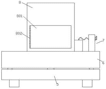
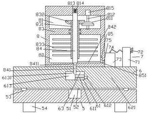
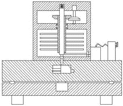
[0021] like Figure 1-Figure 4 As shown, a kind of dedusting facility of the present invention comprises a base 5 and a base frame 6 arranged on the top of the base 5 and is screwed and connected, and the top of the base frame 6 is fixedly provided with a spray box 8, and the spray box 8 The top of the base frame 6 on the right side is provided with a spray device 7, and the base frame 6 below the spray box 8 is provided with a hollow cavity 63, and the inner bottom of the hollow cavity 63 is provided with a guide groove 61, The guide groove 61 is provided with a first helical rod 611 extending left and right, and a guide block 613 is connected to the helical thread on the first helical rod 611, and the top of the guide block 613 is provided with an extension. To the oblique end pushing block 6131 in the hollow cavity 63, the spray box 8 is provided with a first hollow cavity 81 and a second hollow cavity 82, and the first hollow cavity 81 and the second hollow cavity 82 A pa...


PUM


Abstract

The invention discloses dedusting facility. The dedusting facility comprises a base and a base frame which is mounted on the top of the base and is rotatably matched and connected to the base. A spraying box is fixed on the top of the base frame, a spraying device is arranged on the top of the base frame on the right side of the spraying box, a hollow cavity is formed in the base frame below the spraying box, a guide slot is arranged through the bottom of the hollow cavity, a first spiral rod extending left and right is arranged in the guide slot, the first spiral rod is in threaded connected to a guide block in a matched manner, an inclined end pushing block extending into the hollow cavity is arranged on the top of the guide block, a first hollow cavity and a second hollow cavity are formed in the spraying box, a cutting plate is arranged between the first hollow cavity and the second hollow cavity, a stirring and mixing member extending up and down is rotatably connected in the cutting plate in a matched manner, and the extension portion on the top of the stirring and mixing member extends into the first hollow cavity. The dedusting facility disclosed by the invention is simple in structure and convenient to operate, the water using rate and uniformity are improved, waste is reduced, the spraying efficiency and the spraying precise positioning are improved.

Description

technical field [0001] The invention relates to the field of dust removal, in particular to a dust removal facility. Background technique [0002] In construction sites and other places, a large amount of dust will be generated due to construction, and the dust passing through the workers' respiratory tract will seriously affect the workers' lung health. It is necessary to add solvent to the water to achieve a specific effect, but the water and solvent in the existing spray truck are not mixed enough, and the spray head is fixed installation, the spraying position cannot be adjusted according to the actual demand, and it is impossible to spray water mist precise positioning. Contents of the invention [0003] The technical problem to be solved by the present invention is to provide a dust removal facility, which can solve the above-mentioned problems in the prior art. [0004] The present invention is achieved through the following technical solutions: a dust removal fac...

Claims


Application Information

Patent Timeline
Patent Type & Authority Applications(China)
IPC IPC(8): B01D47/06B01F7/18B01F13/00B01F15/00
CPCB01D47/06B01F27/074B01F27/112B01F27/191B01F27/90B01F33/50B01F35/2209B01F35/3204
Inventor 皱承针
Owner YIWU MOYA OPTOELECTRONICS TECH CO LTD
Learn More