
Limiting device used for cut-off deflection rectifying of prefabricated square pile

A technology of limiting device and prefabrication, which is applied in the field of building deviation correction, can solve problems such as easy occurrence of deviation, and achieve the effect of preventing translation

Active Publication Date: 2017-10-17
ZHEJIANG PROVINCE INST OF ARCHITECTURAL DESIGN & RES
View PDF9 Cites 2 Cited by
  • Summary
  • Abstract
  • Description
  • Claims
  • Application Information

AI Technical Summary

Problems solved by technology

[0004] The invention provides a limit device for cutting off and rectifying prefabricated square piles to prevent horizontal displacement when the building is lifted, so as to solve the problem that the building is prone to deflection during the lifting process

Method used


Image

  • Limiting device used for cut-off deflection rectifying of prefabricated square pile
  • Limiting device used for cut-off deflection rectifying of prefabricated square pile
  • Limiting device used for cut-off deflection rectifying of prefabricated square pile

Examples


Embodiment 1

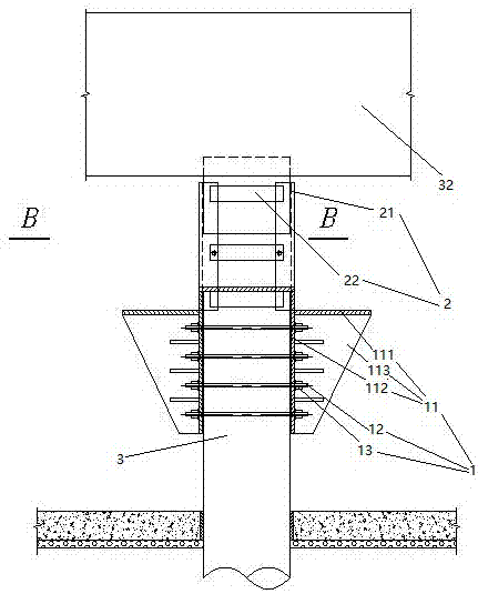
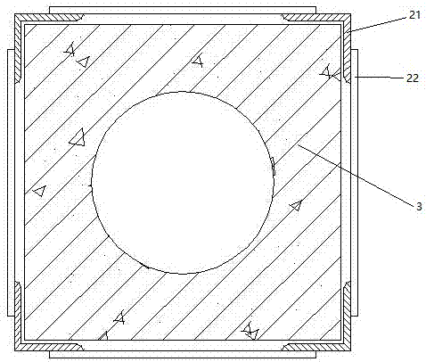
[0020] Embodiment one, see figure 1 , a position-limiting device for truncation and rectification of prefabricated square piles, comprising a support base 1 and a quadrangular prism-shaped position-limiting sleeve 2 . The support base 1 includes two support plates 11 and several bolts 12 . The support board 11 includes a horizontal support board 111 , a vertical support board 112 and a reinforcement board 113 . The horizontal support plate 111 and the vertical support plate 112 are vertically connected together. The reinforcing plate 113 is a right triangle. One right-angled side of the reinforcing plate 113 is connected with the horizontal support plate by welding, and the other right-angled side is connected with the vertical support plate by welding. The two ends of the bolt 12 pass through the vertical support plates of the two support plates one by one and are screwed together with the fixing nut 13 so that the support plates are clamped and fixed on the square piles. ...

Embodiment 2

[0025] Embodiment two, the difference with embodiment one is:

[0026] see Figure 4 , also includes a limit sleeve connection structure 5. Connect the quadrangular prism-shaped spacer sleeve with the support base 1 through the spacer sleeve connection structure 5 with the support base 1 (only the support plate 41 is shown in the support base). Specifically: the limit sleeve connection structure 5 includes a circular sliding rail 51, a circular sliding groove 52 that is rotatably connected on the circular sliding rail, a vertical connecting rod 53 whose lower end is connected together with the circular sliding groove, connected to the support The circular upper slide groove 54 on the bar upper end, the circular upper slide rail 55 that is rotatably connected on the circular upper slide groove and the horizontal connecting rod 56 that one end is connected on the circular upper slide rail. The circular lower rail 51 is fixedly connected with the support base 1 , specifically w...


PUM


Abstract

The invention relates to the technical field of deflection rectifying of buildings. A limiting device used for cut-off deflection rectifying of a prefabricated square pile is characterized by comprising a supporting seat and a quadrangular-prism-shaped limiting sleeve, wherein the supporting seat is used for being fixed to the lower section of the cut-off square pile, and the quadrangular-prism-shaped limiting sleeve is connected to the supporting seat and used for being arranged on the upper section of the cut-off square pile in a sleeving mode; and the quadrangular-prism-shaped limiting sleeve comprises four pieces of angle steel located at the four corners of the quadrangular-prism-shaped limiting sleeve, and horizontal connecting plates connected with the angle steel together. The limiting device used for cut-off deflection rectifying of the prefabricated square pile is used for preventing horizontal displacement when a building is jacked, and the problem that the building is liable to deflect in the jacking process is solved.

Description

technical field [0001] The invention relates to the technical field of building deflection correction, in particular to a limiting device for cutting and rectifying prefabricated square piles. Background technique [0002] Due to the insufficient bearing capacity of the engineering piles and the uneven settlement caused by the difference in the bearing capacity distribution among the engineering piles, the superstructure will tilt. In order to restore the use function of the building, the deviation can be corrected by cutting off the pile body for jacking or forced landing. [0003] On the one hand, due to different geological conditions and hydrological conditions, the surface layer of some sites (part of the pile head) is often soft soil such as silt. After the pile top is cut off, the pile head is in a free state, and the jacking process is prone to deflection; On the one hand, due to the vertical error of the jack installation and other unfavorable factors (such as stro...

Claims


Application Information

Patent Timeline
IPC IPC(8): E02D35/00
CPCE02D35/00
Inventor 杨学林祝文畏
Owner ZHEJIANG PROVINCE INST OF ARCHITECTURAL DESIGN & RES
Learn More