Low-scattering X-ray fluorescence CT imaging system and method

A CT imaging and X-ray technology, applied in the field of X-ray imaging, can solve the problems of fluorescence CT imaging interference, artifacts in reconstructed images, data deviation from the real results, etc., to help diagnosis and treatment, shorten scanning imaging time, The effect of reducing interference

Inactive Publication Date: 2019-05-03
CHONGQING UNIV
View PDF2 Cites 2 Cited by
  • Summary
  • Abstract
  • Description
  • Claims
  • Application Information

AI Technical Summary

Problems solved by technology

In actual situations, X-rays will undergo Compton scattering during the interaction with matter, and the signal reaching the detector may partly come from scattering. These scattered photons make the detected data deviate from the real result, and cause the reconstructed image to appear Artifacts, causing certain interference to fluorescence CT imaging

Method used


Image

  • Low-scattering X-ray fluorescence CT imaging system and method
  • Low-scattering X-ray fluorescence CT imaging system and method
  • Low-scattering X-ray fluorescence CT imaging system and method

Examples


Embodiment 1

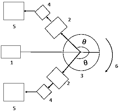
[0024] figure 2 It is a structural block diagram of Solution 1 of the present invention, including a fan beam X-ray source 1 , an X-ray fluorescence detector 4 , a pinhole collimator 2 and a data processing system 5 . The tested sample 3 is placed on the sample stage, and can translate or rotate with the sample stage.

[0025] The X-ray fluorescence detector 4 is arranged between the X-ray source and the sample stage, and a pinhole collimator 2 is arranged in front of the detector. The X-ray fluorescence detector adopts 8 surface detectors, and the fluorescence detectors are divided into two groups, a group of 4 (see image 3 ), symmetrically placed at a position with an included angle of 90°-180° to the incident light, so that fluorescence data at two rotation angles can be obtained in one scan. Cut the number of sample stage rotations in half and increase scan speed. The detected sample interacts with incident X-rays to generate fluorescence, and part of the fluorescence...

Embodiment 2

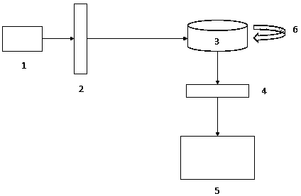
[0027] Figure 4 The structural block diagram of the second solution of the present invention, the system includes an X-ray source 1 , an X-ray fluorescence detector 4 , and a data processing system 5 . The tested sample 3 is placed on the sample stage, and can translate or rotate with the sample stage.

[0028] The X-ray fluorescence detector 4 adopts a surface detector, which is arranged at a position at an angle of 180° to the incident X-ray, and between the ray source 1 and the detected sample 3. At this time, the Compton scattered photon energy is the smallest, and it is easy to Compton background is distinguished from fluorescent signal. The X-ray source 1 is a pencil-shaped X-ray source, and a small hole is left in the center of the detector. The pencil-shaped X-ray passes through the small hole and is irradiated on the tested sample 3. The X-ray source 1, the center of the small hole and the center of the tested sample 3 at the same level.

[0029] The X-ray light e...

Embodiment 3

[0031] The fluorescent CT imaging method using the above system includes the following steps:

[0032] (1) The X-ray light emitted by the X-ray source is irradiated on the sample to be tested, and the X-ray interacts with the high-Z substance in the sample to generate fluorescence;

[0033] (2) Utilize a fluorescence detector to detect the X-ray fluorescence, and the scheme 2 fluorescence detector is placed between the X-ray source and the sample stage; image 3 Translate the sample in the direction of the middle arrow 7, repeat the scanning process, so that the detector can detect all the fluorescence in the area, and obtain a set of X-ray fluorescence spectrum data; scheme 1 The fluorescence detector is placed at 90°-180° to the incident X-ray light ° between. Only fluorescence data passing through the pinhole is received.

[0034] (3) analyzing and processing the X-ray fluorescence spectrum to obtain a set of projection data of X-ray fluorescence CT;

[0035] (4) Press at ...


PUM


Abstract

The invention relates to a low-scattering X-ray fluorescence CT imaging system and method. The system comprises a light source, X-ray fluorescence detectors, and a data processing system. The light source is a fan-shaped beam X-ray source. The detectors are eight minitype fluorescent detectors and are classified into two groups; and each group includes four detectors. Pinhole collimators are addedin front of the detectors and are arranged at the two sides of an incident X-ray beam symmetrically; and an included angle between the collimators and the incident X-rays are 90 to 180 degrees. Fluorescent light passes through the pinhole collimators and then is received by the fluorescence detectors; the data processing system carries out conversion to obtain projection data; and then an elementdistribution structure chart of the sample is reconstructed. Therefore, the resolution and contrast of different soft tissues of medical CT images can be increased; and the interference on the photons by the Compton scattering can be reduced.

Description

technical field [0001] The invention relates to an X-ray imaging method, in particular to a non-synchronous radiation micro-beam X-ray fluorescence CT method. Background technique [0002] As a non-invasive imaging technology, X-ray Computed Tomography (X-CT) has been widely used in clinical medical diagnosis and has become one of the important means of clinical disease diagnosis. In recent years, a new type of X-ray technology, X-ray Fluorescence Computed Tomography (XFCT), has emerged in the field of X-ray imaging. This technology is an organic combination of X-ray CT and X-ray fluorescence analysis. The combined product uses incident X-rays to excite the high atomic number elements in the sample to generate fluorescence, which can efficiently obtain quantitative information on the distribution of specific elements in the imaging target. At the same time, combined with transmission CT technology, the internal structure information of the sample can be restored. Because X-...

Claims


Application Information

Patent Timeline
Patent Type & Authority Applications(China)
IPC IPC(8): G01N23/223
Inventor 郭静冯鹏邓露珍何鹏魏彪
Owner CHONGQING UNIV
Why Eureka
Try Eureka