Harvesting machinery cleaning system fan control method, controller and control system

A harvesting machine and control method technology, which is applied to the control, controller and control system of the fan of the cleaning system when the harvesting machine is operating on the slope, and the control field of the fan of the harvesting machine's cleaning system, which can solve the problem of poor cleaning effect and manipulation. High intensity, short working time without failure, etc., to achieve the effect of simple manual operation

Active Publication Date: 2017-10-20
ZOOMLION HEAVY MASCH CO LTD
View PDF9 Cites 6 Cited by
  • Summary
  • Abstract
  • Description
  • Claims
  • Application Information

AI Technical Summary

Problems solved by technology

Most of the current grain combine harvesters are only equipped with alarm devices for clogging and full grain tanks, etc., and generally lack intelligent monitoring devices such as working parameters and performance monitoring, electric / automatic adjustment of working parameters, etc., making the machine performance unstable , the operating efficiency depends on the driver's manual proficiency, and the operating intensity is high, the blockage faults occur frequently, and the trouble-free working time is short, which cannot meet the operational requirements of large-scale grain production and grain rotation areas in my country.
[0005] Therefore, there is a need in the prior art for a control method for the harvesting machine cleaning fan that can solve the aforementioned problems, especially, when the harvesting machine is harvesting on a slope, the control of the cleaning fan is needed to solve the problems of the prior art. The problem of poor cleaning effect when the middle harvesting machine works on slopes

Method used


Image

  • Harvesting machinery cleaning system fan control method, controller and control system
  • Harvesting machinery cleaning system fan control method, controller and control system
  • Harvesting machinery cleaning system fan control method, controller and control system

Examples


Embodiment Construction

[0029] Exemplary embodiments of the present invention will be described in detail below with reference to the accompanying drawings. The description of the exemplary embodiments is for the purpose of illustration only, and in no way limits the invention and its application or usage.

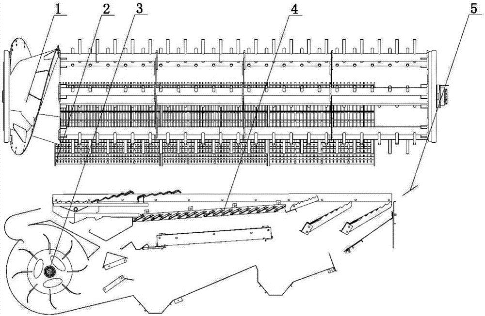
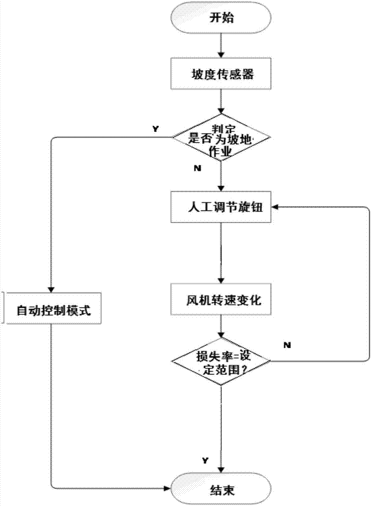
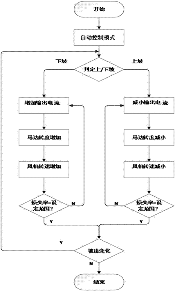
[0030] figure 1 is a flow chart of the control mode according to the control method of the present invention; figure 2 It is a flow chart of the automatic control mode according to the control method of the present invention when working on a slope; Figure 3A is a schematic structural diagram of the cleaning system; Figure 3B It is a schematic structural diagram of the fan assembly of the cleaning system; Figure 4 It is the operation diagram of the cleaning system when the vehicle is operating on a flat road; Figure 5 It is a schematic diagram of the cleaning system when the vehicle is working downhill. Image 6 It is a schematic diagram of the cleaning system when the vehicle is workin...


PUM


Abstract

The invention discloses a harvesting machinery cleaning system fan control method which includes the steps: 1) defining an inclined angle range alpha1-alpha2 as an ideal inclined angle range of a harvesting machinery cleaning system, defining time t as ideal tilted time of the harvesting machinery cleaning system, defining loss ratio w as ideal loss ratio of the harvesting machinery cleaning system, and defining rotating speed v as ideal rotating speed of a harvesting machinery cleaning system fan; 2) sensing an inclined angle alpha s, tilted time ts, loss ratio ws and current rotating speed vs of the fan; 3) comparing the inclined angle alpha s, the tilted time ts and the loss ratio ws sensed in the step 2) with the ideal inclined angle range alpha1-alpha2, the ideal tilted time t and the ideal loss ratio w, and judging whether the current rotating speed v needs to be changed or not; 4) adjusting the current rotating speed v until the sensed loss ratio ws returns into the range of the ideal loss ratio w when the current rotating speed v needs to be changed in the step 3). The invention further provides a controller and a control system.

Description

technical field [0001] The invention relates to the field of agricultural machinery, in particular to a control method, a controller and a control system for a fan of a harvesting machinery cleaning system. It is especially suitable for controlling the fan of the cleaning system when the harvesting machine is working on a slope. Background technique [0002] The technical background related to the present invention will be described below, but these descriptions do not necessarily constitute the prior art of the present invention. [0003] As we all know, for example, the cleaning device of the harvesting machine of the combine harvester is the "digestive system" of the machine, and it is also the core working part that affects the operation quality, efficiency and adaptability of the harvesting machine. Most of the grain combine harvesters sold on the market in our country adopt the traditional air screen type cleaning device. The cleaning fan is an important part of the c...

Claims


Application Information

Patent Timeline
IPC IPC(8): A01F12/44
CPCA01F12/446
Inventor 张恒张岳生王世超王慧敏
Owner ZOOMLION HEAVY MASCH CO LTD
Why Eureka
Try Eureka