On-position dressing method for ball head grinding wheel during ultra-precision grinding of special-shaped thin-wall structural member

A thin-walled structural part and ultra-precision technology, which is applied to the parts of grinding machine tools, grinding/polishing equipment, abrasive surface adjustment devices, etc., can solve the problems of wasting grinding wheels, affecting the surface quality of workpieces, and increasing the overall processing time. Achieve high retouching quality results

Active Publication Date: 2017-10-20
HARBIN INST OF TECH
View PDF14 Cites 5 Cited by
  • Summary
  • Abstract
  • Description
  • Claims
  • Application Information

AI Technical Summary

Problems solved by technology

However, these advantages also make it difficult to dress metal-based diamond grinding wheels. The existing mechanical dressing methods are difficult to achieve high-precision dressing, so EDM dressing is required.
For ultra-precision grinding of small-diameter metal-based diamond ball-end grinding wheels, the wear of the ball-end grinding wheel is a problem that cannot be ignored. The worn ball-end grinding wheel will seriously affect the surface shape accuracy and surface quality of the workpiece, so It is necessary to propose a method for EDM dressing of in-situ ball head grinding wheel
At the same time, the judgment of the timing of grinding wheel dressing is also a very critical factor. Too early dressing will waste the grinding wheel and increase the overall processing time. Too late dressing will affect the surface quality of the workpiece after ultra-precision grinding

Method used


Image

  • On-position dressing method for ball head grinding wheel during ultra-precision grinding of special-shaped thin-wall structural member
  • On-position dressing method for ball head grinding wheel during ultra-precision grinding of special-shaped thin-wall structural member
  • On-position dressing method for ball head grinding wheel during ultra-precision grinding of special-shaped thin-wall structural member

Examples


Embodiment Construction

[0063] The following will clearly and completely describe the technical solutions in the embodiments of the present invention with reference to the accompanying drawings in the embodiments of the present invention. Obviously, the described embodiments are only some, not all, embodiments of the present invention. Based on the embodiments of the present invention, all other embodiments obtained by persons of ordinary skill in the art without creative efforts fall within the protection scope of the present invention.

[0064] It should be noted that, in the case of no conflict, the embodiments of the present invention and the features in the embodiments can be combined with each other.

[0065] The present invention will be further described below in conjunction with the accompanying drawings and specific embodiments, but not as a limitation of the present invention.

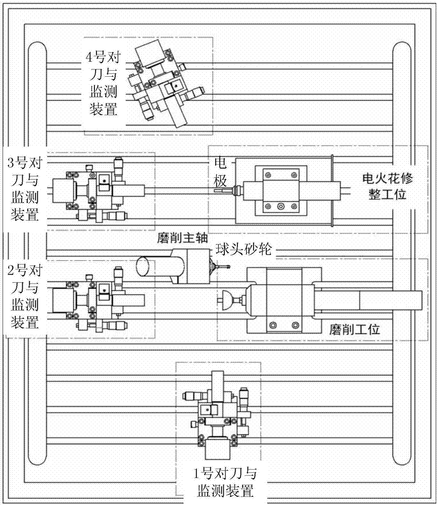
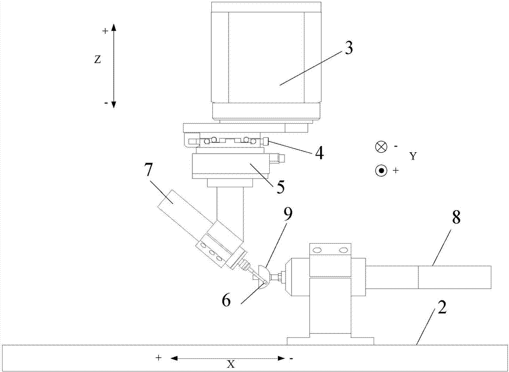
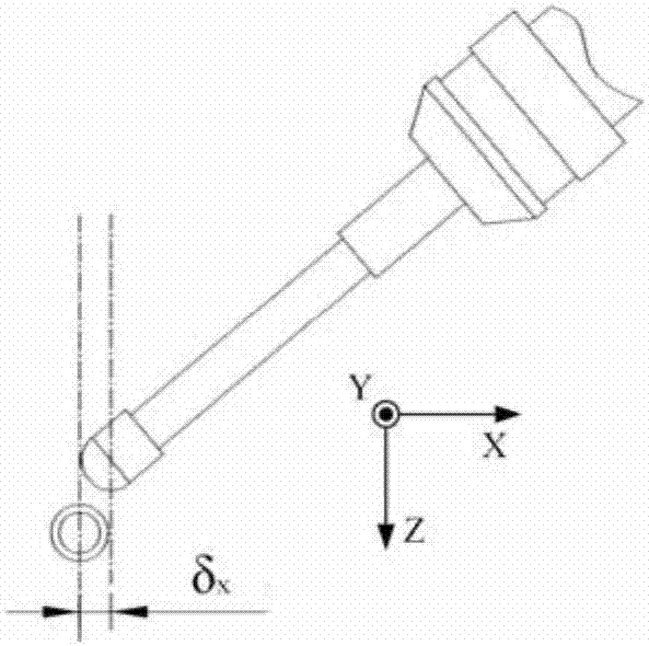
[0066] The in-situ dressing method of the ball-end grinding wheel described in this embodiment is based on the p...


PUM


Abstract

The invention provides an on-position dressing method for a ball head grinding wheel during ultra-precision grinding of a special-shaped thin-wall structural member to realize easy operation and a convenient and rapid tool-setting process without need of repeated dressing and grinding and ensure the higher dressing quality of the grinding wheel, and relates to a processing technology. First, a third tool-setting and monitoring device and a fourth tool-setting and monitoring device are utilized to calibrate ball center coordinates and dressing electrode location coordinates when the ball head grinding wheel is at a dressing station; and the location coordinates of the distance from the ball head grinding wheel to a first tool-setting and monitoring device are calibrated; during the ultra-precision grinding process, the ball head grinding wheel is monitored and the abrasion status of the grinding wheel is judged; ultra-precision grinding is suspended so as to conduct on-position dressing on the ball head grinding wheel, the fourth tool-setting and monitoring device is adopted to monitor the electric spark discharging status and the dressing quality of the ball head grinding wheel; and the ball center position of the grinding wheel is adjusted after dressing, and procedure origin during grinding machining is searched to continue the unfinished ultra-precision grinding processing.

Description

technical field [0001] The invention relates to a processing technology, in particular to an in-situ dressing method of a ball-end grinding wheel for ultra-precision grinding of special-shaped thin-walled structural parts. Background technique [0002] With the development of science and technology, more and more stringent requirements are put forward for the processing quality of parts. At the same time, the materials used for parts tend to be hard and brittle materials such as fused quartz and ceramics. Such materials have good chemical stability and high hardness. characteristics, but it also brings difficulties to its processing. In order to meet the processing requirements of such materials, ultra-precision grinding is a very promising processing method. For the ultra-precision grinding of concave parts with special-shaped structures and small radius of curvature, conventional grinding wheels cannot achieve the grinding process, so a small-sized metal-based diamond bal...

Claims


Application Information

Patent Timeline
Patent Type & Authority Applications(China)
IPC IPC(8): B24B53/06B24B53/12
CPCB24B53/06B24B53/12
Inventor 陈明君王廷章程健刘赫男吴春亚方针于波
Owner HARBIN INST OF TECH
Why Eureka
Try Eureka