disk drive

A disk drive and stopper technology, which is applied in the direction of instruments, carrier covers, recording information storage, etc., can solve the problems of bad influence of data reading/writing, noise applied to the disk, etc.

Active Publication Date: 2019-08-16
KK TOSHIBA
View PDF2 Cites 0 Cited by
  • Summary
  • Abstract
  • Description
  • Claims
  • Application Information

AI Technical Summary

Problems solved by technology

When such an HDD is used in an external device, when an external magnetic field such as an electromagnetic wave acts on the HDD casing from the external device, noise is applied to the disk, which adversely affects the reading / writing of data by the magnetic head.

Method used


Image

  • disk drive
  • disk drive
  • disk drive

Examples


no. 1 approach

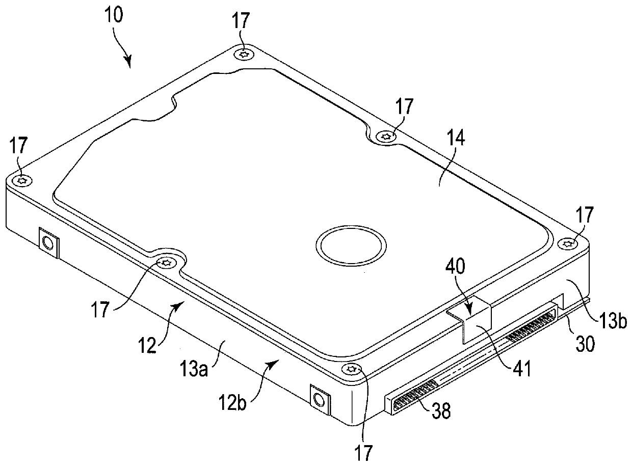
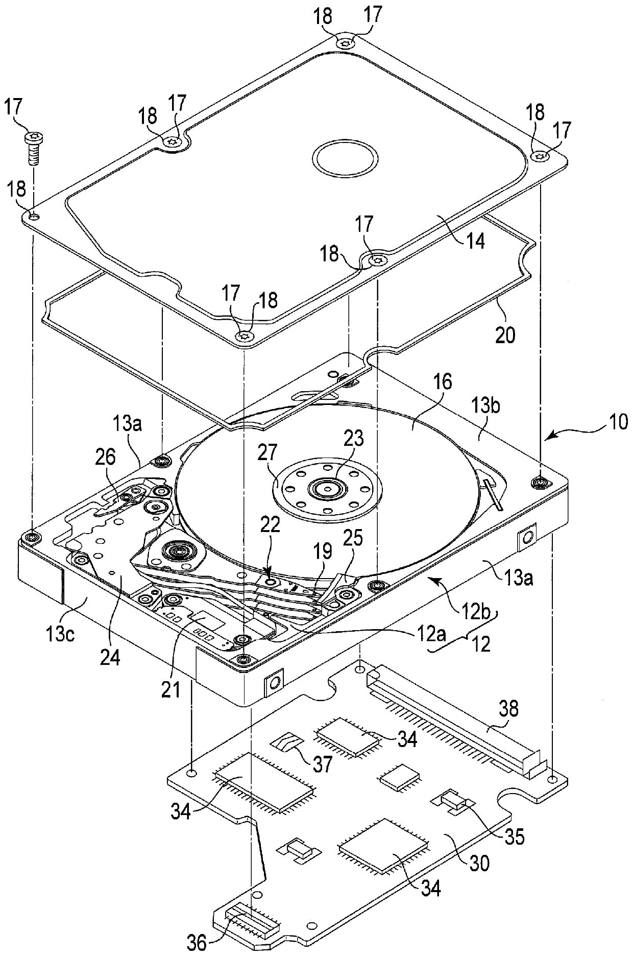
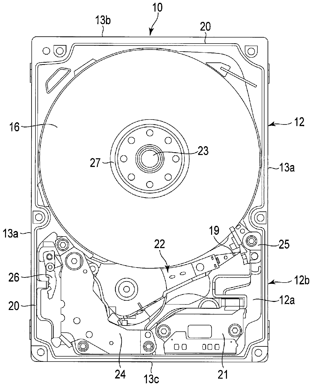
[0017] A hard disk drive (HDD) according to the first embodiment as a disk drive will be described in detail.

[0018] figure 1 is a perspective view showing the HDD according to the first embodiment, figure 2 It is an exploded perspective view showing HDD disassembled, image 3 It is a plan view showing the internal structure of the HDD.

[0019] Such as Figure 1 to Figure 3 As shown, the HDD includes a casing 10 . The casing 10 has a rectangular box-shaped base 12 with an open top surface and a rectangular plate-shaped top cover 14 . The top cover 14 is screwed to the base 12 through a plurality of screw members 17 to close the upper opening of the base 12 . The base 12 has a rectangular bottom wall 12 a and side walls 12 b erected along the periphery of the bottom wall, and is integrally formed of metal materials such as aluminum and stainless steel. The side wall 12b of the base 12 includes a pair of long side walls 13a opposite to each other and a first short side...

no. 2 approach

[0041] Figure 7 is a perspective view showing an HDD according to the second embodiment, Figure 8 It is an exploded perspective view showing the first short side wall 13b side of the HDD according to the second embodiment disassembled, Figure 9 It is a side view showing the HDD viewed from the side of the first short side wall 13b.

[0042] Such as Figure 7 and Figure 8 As shown, in this embodiment, the structure of the conduction portion 40 of the housing 10 includes: a convex portion 42 provided on the side edge of the short side of the top cover 14; and a first short side wall of the base 12 The recess 44 is formed in the upper part of 13b. The convex portion 42 is formed as a rectangular convex portion protruding toward the base 12 side by bending or drawing a part of the top cover 14 . Moreover, the convex part 42 is provided in the substantially center part of the short side of the top cover 14. As shown in FIG.

[0043] The recess 44 of the first short side w...


PUM


Abstract

A disk drive includes a metal base that has a rectangular bottom wall and side walls formed on each side of the rectangular bottom wall, the side walls including a first side wall on a shorter side, a metal cover that is fixed to the metal base with a plurality of metal screws, including two screws disposed at opposite ends of the side wall, a gap being formed between an upper end of the first side wall and the metal cover, a magnetic disk disposed on the metal base, at a position offset from a center of the metal base in a longitudinal direction towards the first side wall, and a head. The first side wall and the metal cover are electrically connected at an intermediate position of the first side wall between said opposite ends of the first side wall.

Description

[0001] This application claims the priority of the earlier application with U.S. provisional patent application 62 / 319, No. 683 (filing date: April 7, 2016). This application incorporates the entire content of the earlier application by reference to this earlier application. technical field [0002] Embodiments of the invention relate to disk drives. Background technique [0003] A hard disk drive (HDD) functioning as a disk drive includes, for example: a rectangular casing; a disk-shaped recording medium (disk) disposed in the casing; into the magnetic head. The casing has a rectangular base and a plate-shaped top cover screwed to the base. When such an HDD is used in an external device, when an external magnetic field such as an electromagnetic wave acts on the HDD casing from the external device, noise is applied to the disk, which adversely affects the reading / writing of data by the magnetic head. . Therefore, the HDD preferably has high electromagnetic susceptibilit...

Claims


Application Information

Patent Timeline
Patent Type & Authority Patents(China)
IPC IPC(8): G11B5/48G11B5/49G11B33/14
CPCG11B5/488G11B5/4907G11B33/1493G11B25/043G11B33/1466G11B33/027
Inventor 山崎信义辻村俊博
Owner KK TOSHIBA
Why Eureka
Try Eureka