Roller brush unit concentric snapping structure for cleaning wafers

A joint structure and rolling brush technology, which is applied in the field of concentric clamping structure of rolling brush units, can solve the problems of waste, poor sealing effect of O-ring, and short service life.

Inactive Publication Date: 2017-10-20
BEIJING SEMICON EQUIP INST THE 45TH RES INST OF CETC
View PDF3 Cites 5 Cited by
  • Summary
  • Abstract
  • Description
  • Claims
  • Application Information

AI Technical Summary

Problems solved by technology

[0004] Another defect of the traditional inertial unit is that the idler shaft and other components are sealed with O-rings. The O-rings have poor sealing effect, short service life, and need to be replaced frequently, which not only causes various wastes but also reduces equipment utilization.

Method used


Image

  • Roller brush unit concentric snapping structure for cleaning wafers
  • Roller brush unit concentric snapping structure for cleaning wafers
  • Roller brush unit concentric snapping structure for cleaning wafers

Examples


Embodiment Construction

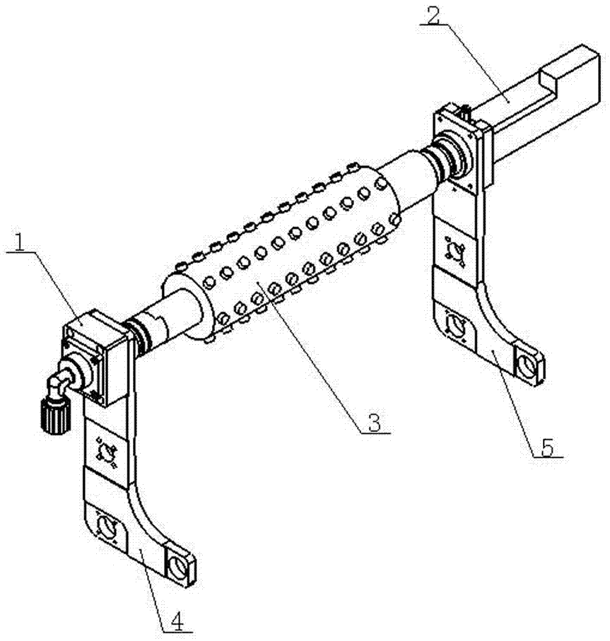
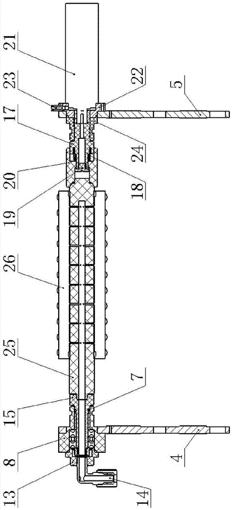
[0025] Such as figure 1 , figure 2 As shown, the concentric clamping structure of the rolling brush unit for cleaning wafers of the present invention includes a left swing frame 4, an inertia unit 1 fixed on the left swing frame 4, a right swing frame 5, a drive unit 2 fixed on the right swing frame 5, an inertia unit A roller brush unit 3 with a PVA roller brush 26 is clamped between the unit 1 and the drive unit 2 .

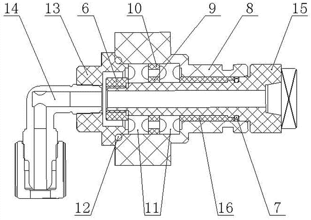
[0026] Such as figure 2 , image 3 , Figure 4 As shown, the inert unit 1 includes a mounting seat 8 whose central hole is a two-step round hole, and a bearing group composed of an inner spacer 9, an outer spacer 10 and a bearing 11 is installed in the large hole at the left end of the second-step round hole. A spacer 16 is installed in the small hole at the right end of the round hole. The spacer 16, the bearing 11 and the mounting seat 8 are jointly installed with a central hole as a water supply channel and a three-step idler shaft 15 on the outside. T...


PUM


Abstract

The invention provides a roller brush unit concentric snapping structure for cleaning wafers. An elastic telescopic snapping structure is arranged on a driving unit for realizing quick snapping and changing. The roller brush unit concentric snapping structure reduces a non-coaxiality manufacturing tolerance between a driving shaft and an idle shaft. The rotating shaft and the driving shaft or the idle shaft of the roller brush utilize a structure form in which a conical hole and a conical shaft are connected in a flexible concentric positioning manner and a square hole and a square shaft are connected in a rigid engaging force transmission manner, thereby reducing a rigid connection degree and the rotating shaft, the driving shaft and the idle shaft of the roller brush, attenuating rotation bounce of the rotating shaft of the roller brush, and eliminating impact of roller brush bounce to a wafer. A glyd ring is arranged for realizing bidirectional sealing. Not only is bidirectional leakage of the idle shaft is settled, but also a function of supporting the idle shaft in concentric rotation is performed. The roller brush unit concentric snapping structure for cleaning the wafers is used for a cleaning system after chemically mechanical polishing (CMP) of the wafer, thereby preventing impact damage of the wafer by the roller brush, improving wafer product quality, reducing sealing gasket changing frequency and prolonging maintenance period of the cleaning equipment.

Description

technical field [0001] The invention relates to a wafer cleaning device, in particular to a concentric clamping structure of a rolling brush unit for chemically cleaning a wafer. Background technique [0002] The cleaning after wafer chemical mechanical polishing (CMP) is completed by the rolling drag force of the PVA roller brush on the roller brush unit in the equipment and the scouring of the chemical solution. The PVA rolling brush is overcoated on the rotating shaft of the rotating brush and scrubs the wafer along with the rotation of the rotating shaft of the rotating brush. One end of the traditional rolling brush shaft is connected to the drive shaft of the drive unit, and the other end is connected to the idle shaft of the inertia unit. The connection methods are realized by inserting square holes and square shafts into each other. In this connection structure, the drive shaft and the idle shaft exist as two independent bodies, and there are non-parallel and non-co...

Claims


Application Information

Patent Timeline
Patent Type & Authority Applications(China)
IPC IPC(8): H01L21/67B08B1/04
CPCB08B1/002B08B1/04H01L21/67046
Inventor 陶利权柳滨史霄熊朋周庆亚佀海燕
Owner BEIJING SEMICON EQUIP INST THE 45TH RES INST OF CETC
Why Eureka
Try Eureka