Continuous drilling machine

A threaded connection and spindle technology, applied in drilling equipment, earthwork drilling, drilling equipment and methods, etc., can solve the problems of slipping and wear, reducing the service life of the drill bit, and small elastic deformation of the drill string.

Inactive Publication Date: 2016-02-03
SICHUAN FEIXIANG ENERGY CO LTD
View PDF7 Cites 0 Cited by
  • Summary
  • Abstract
  • Description
  • Claims
  • Application Information

AI Technical Summary

Problems solved by technology

[0003] Due to the low drilling efficiency of intermittent drilling, it will also bring continuous impact damage and sliding wear to the drilling edge of the drill bit. In addition, the drill pipes, drill collars and other drilling tools that make up the drill string are all rigid. Rods, under the gravity similar to the drilling pressure, the elastic deformation of the drill string is actually very small, that is, the actual drilling depth of the drill bit after a single drill is relatively shallow, so the current drill string combination has the following deficiencies: Low feed efficiency; reduce the service life of the drill bit; reduce the service life of the drill tool

Method used


Image

  • Continuous drilling machine
  • Continuous drilling machine
  • Continuous drilling machine

Examples


no. 1 example

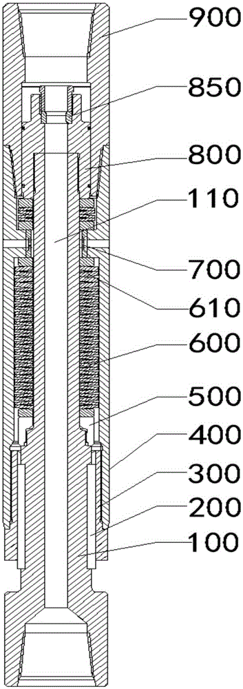
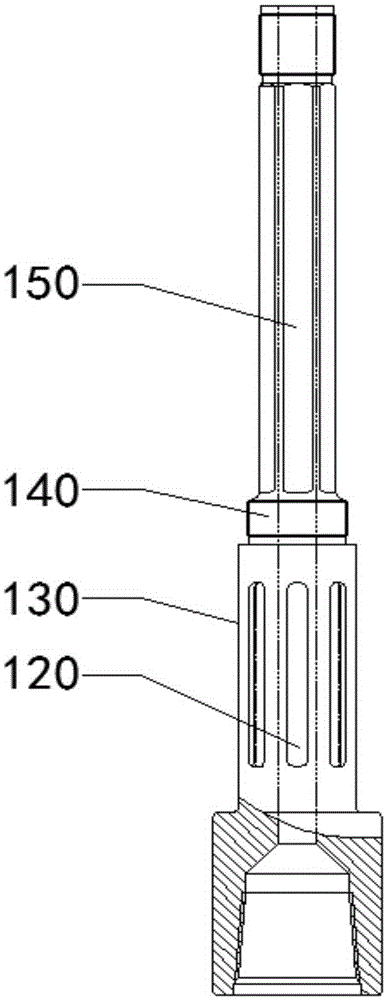
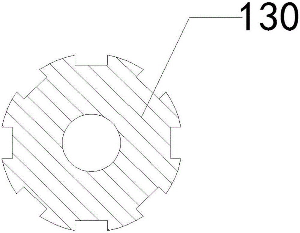
[0040] For the first embodiment, refer to Figure 1-8, the continuous drilling device includes a housing 400 and a main shaft 100, the bottom of the inner wall of the housing 400 is threaded with a first sliding sleeve 300, and a spline hole is arranged in the first sliding sleeve 300, and the spline hole The inner wall of the main shaft 100 is provided with a spline groove 120, and the outer wall of the main shaft 100 is provided with a plurality of key grooves 120, and the plurality of key grooves 120 are arranged at intervals along the circumferential direction of the main shaft 100, and the length direction of each key groove 120 is consistent with that of the main shaft 100. The length direction is the same, the keyway 120 is provided with a sliding key 200 matching the spline groove 120, the inner wall of the housing 400 is also provided with an annular boss, and the outer wall of the main shaft 100 is also provided with an anti-drop Nut 500, the outer diameter of the an...

no. 2 example

[0082] For the second embodiment, refer to Figure 9-10 , the implementation principle and technical effect of the device provided by the embodiment of the present invention are the same as those of the foregoing embodiment. For brief description, for the parts not mentioned in the device embodiment, reference may be made to the corresponding content in the foregoing embodiment.

[0083] In this embodiment, a pressure-assisting adjustment core 910 and an adjustment core mounting seat 920 for fixing the pressure-assisting adjustment core 910 are arranged in the installation cavity. into the inner hole of the pressure-assist adjusting sleeve 850, and the adjusting core mounting base 920 is detachably connected in the mounting cavity.

[0084] Wherein, the inner wall of the installation cavity is provided with a step surface, the bottom edge of the adjustment core mounting seat 920 is supported on the step surface, and the top is pressed against by a snap spring, thereby ensuring...


PUM


Abstract

The invention provides a continuous drilling machine, and belongs to the field of well drilling tools. The continuous drilling machine comprises a shell and a spindle. A first slide sleeve is connected with the bottom of the inner wall of the shell in a threaded manner, spline holes are formed in the first slide sleeve, spline grooves are formed in the inner walls of the spline holes, a plurality of key grooves are formed in the outer wall of the spindle, slide keys which are matched with the spline grooves are arranged in the key grooves, an annular boss is further arranged on the inner wall of the shell, an anti-falling nut is further arranged on the outer wall of the spindle, the outer diameter of the anti-falling nut is larger than the inner diameter of the first slide sleeve, a first disc spring combination column sleeves the spindle, a plurality of disc springs are overlaid on one another to form the first disc spring combination column, the top of the first disc spring combination column is butted to the annular boss, the bottom of the first disc spring combination column is butted to the anti-falling nut, and a through hole for circulating well drilling liquid is formed inside the spindle. The continuous drilling machine has the advantages that the action distances of drill pressures can be obviously extended in each single bit feeding procedure, the continuous drilling depths of drill bits can be obviously increased in each single bit feeding procedure, and the drill bits can be continuously drilled over long distances.

Description

technical field [0001] The present invention relates to the field of drilling tools, in particular, to a continuous drilling device. Background technique [0002] In the current petroleum or other geological drilling, the basic combination of the drill string is drill pipe + drill collar + drill bit. Add power drilling tools such as stabilizers and screw drilling tools that play a central role. During the drilling process, due to the control of the intermittent drilling mode of manual operation, the drilling of the drill bit to the bottom of the well is actually carried out in the mode of intermittent drilling, and after each drilling, the continuous drilling of the drill bit The drilling depth mainly depends on the elastic deformation of the drill string under the drilling pressure. [0003] Due to the low drilling efficiency of intermittent drilling, it will also bring continuous impact damage and sliding wear to the drilling edge of the drill bit. In addition, the drill...

Claims


Application Information

Patent Timeline
Patent Type & Authority Applications(China)
IPC IPC(8): E21B7/00
Inventor 李少江
Owner SICHUAN FEIXIANG ENERGY CO LTD
Why Eureka
Try Eureka