Charging device and charging method

A charging device and charging interface technology, which is applied to circuit devices, battery circuit devices, charging/discharging current/voltage regulation, etc., to achieve the effect of improving output efficiency

Inactive Publication Date: 2017-10-20
SHANGHAI IND U TECH RES INST
View PDF3 Cites 2 Cited by
  • Summary
  • Abstract
  • Description
  • Claims
  • Application Information

AI Technical Summary

Problems solved by technology

This makes the energy unit unable to work stably near the maximum power point all the time

Method used


Image

  • Charging device and charging method
  • Charging device and charging method

Examples


Embodiment Construction

[0015] The specific implementation of the charging device and the charging method provided by the present invention will be described in detail below in conjunction with the accompanying drawings.

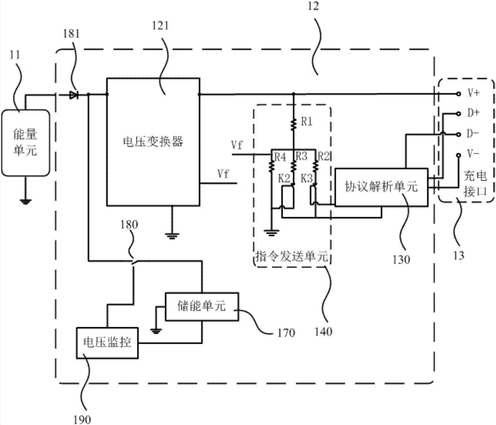
[0016] attached figure 1 Shown is a schematic structural diagram of a specific embodiment of the charging device of the present invention, including an energy unit 11 , a charging module 12 and a charging interface 13 . The electric energy output by the energy unit 11 is converted by the charging module 12 and charged externally through the charging interface 13 . The terminal to be charged can be a mobile phone or a tablet computer, etc. For a terminal that supports fast charging, the charging interface 13 is required to provide it with a charging voltage higher than 5V, usually including multiple specifications such as 5V / 2A, 9V / 1.67A, 12V / 1.5A, etc. This requires the charging module 12 to be adjusted according to the situation.

[0017] In this specific embodiment, in order t...


PUM


Abstract

The invention discloses a charging device and a charging method. The charging device includes an energy unit, a charging module and a charging interface. The charging module includes a voltage changer and a voltage stabilizing module. The voltage stabilizing module includes an energy storage unit connected with the energy unit electrically; a charge-discharge control switch whose first terminal is connected with the energy storage unit electrically and whose second terminal is connected with the energy unit electrically via a reverse protection diode; a voltage monitoring unit connected with a control terminal of the charge-discharge switch and the energy storage unit electrically and used for controlling the on and off of the charge-discharge control switch based on output voltage values of the energy storage unit.

Description

technical field [0001] The invention relates to the field of circuit design, in particular to a charging device and a charging method. Background technique [0002] The portable charging devices in the prior art all use an energy unit capable of providing energy to charge another terminal that needs to be charged. The energy unit is, for example, a lithium battery or a solar panel. However, some energy units have a maximum power point due to their internal structural characteristics. Only when they work near the maximum power point can the energy unit have the highest working efficiency. However, the voltage and current required by the terminal to be charged often change, especially for a terminal supporting fast charging, the required voltage and current may change at any time. This makes the energy unit unable to work stably near the maximum power point all the time. Therefore, it is an urgent problem to be solved in the prior art to provide a technical solution capable...

Claims


Application Information

Patent Timeline
Patent Type & Authority Applications(China)
IPC IPC(8): H02J7/00H02J7/34
CPCH02J7/00H02J7/007H02J7/34
Inventor 张久庆卞建涛
Owner SHANGHAI IND U TECH RES INST
Why Eureka
Try Eureka