Light source mode alignment device and method, passive optical network system

a light source mode and alignment method technology, applied in the field of optical communication, can solve the problems of not very mature wdm-pon, difficult to satisfy video services, and need to be improved, and achieve the effects of reliable operation of pon system, low cost, and strong anti-interference capability

Inactive Publication Date: 2011-04-19
HUAWEI TECH CO LTD
View PDF8 Cites 15 Cited by
  • Summary
  • Abstract
  • Description
  • Claims
  • Application Information

AI Technical Summary

Benefits of technology

[0007]Accordingly, an embodiment of the present disclosure provides a light source mode alignment device and method, so as to realize an automatic alignment between a wavelength and a longitudinal mode of a laser, thereby ensuring a stable output power of the laser.
[0008]An embodiment of the present disclosure provides a passive optical network (PON) system, in which a light source in the PON system outputs a stable power, thereby ensuring a reliable operation of the PON system.
[0016]In the embodiments of the present disclosure, the automatic alignment (without manual calibration) between the wavelength and the longitudinal mode of the laser is realized at a low cost (a common AWG not limited to an athermal AWG, may be used), so as to compensate influences brought by the temperature variation. Moreover, under the interferences of an optical power drift and a wavelength drift resulted from various factors, the light source mode alignment device according to the embodiment of the present disclosure can still realize the mode alignment, that is because the phase information of the signals is used, which has a strong anti-interference capability. The light source mode alignment device is adopted as a light source in the OLT and / or ONU of the PON system, which is capable of outputting a stable power, thereby ensuring a reliable operation of the PON system.

Problems solved by technology

Although the 2 Mbps bandwidth of a digital subscriber line (DSL) is sufficient for the current data transmission services, it is difficult to satisfy the video services.
However, because the time division multiplexing and burst mode technologies are employed, the cost of the system is rather high.
However, on the whole, the WDM-PON is not very mature and needs to be improved in many aspects, for example, colorless light source, temperature compensation, network upgrade, and so on.
In order to solve the problems caused by the mode misalignment, one common solution is to coat an anti-reflection film on a front end surface of the FP-LD to weaken the modes of the FP-LD, which nevertheless introduces a large power penalty.
However, the mismatch between the modes of −0.2 nm and +0.07 nm results in a power penalty of 3 dB.
In addition, during the actual implementation, the inventors found that, if a specific wavelength calibration is not performed on each FP-LD, the mismatch of the modes may occur to a great extent, which results in a difference between optical network units (ONUs), thereby further affecting the reliable operation of the system.
On the other aspect, if the wavelength calibration is performed on each FP-LD, the element cost and maintenance cost are greatly increased.
If the AWG is not an athermal AWG of a high cost, the common FP-LD wavelength control process is no longer feasible, due to the drift of the AWG channel.

Method used


Image

  • Light source mode alignment device and method, passive optical network system
  • Light source mode alignment device and method, passive optical network system
  • Light source mode alignment device and method, passive optical network system

Examples


first embodiment

[0056]1) A An Analog Signal Processing Unit and an MPD Inside a Laser are Employed.

[0057]FIG. 5 is a structural view of a light source mode alignment device according to a first embodiment of the present disclosure.

[0058]An incident light enters an FP-LD 501 in a general laser module 50 via a circulator 51. The FP-LD 501 as an optical pump excites an FP-LD chip to generate a laser. One part of the laser (a large part of the energy) is emitted outwards via a front end surface of the FP-LD chip to form an output light, and the other part forms a back light of the laser via a rear end surface of the FP-LD chip. The back light is detected and converted into a current signal by an MPD 502. The current signal is amplified into a voltage signal by a transimpedance amplifier 503 located in the general laser module 50. Then, the voltage signal is transmitted to a signal processing unit 52. In this embodiment, the signal processing unit 52 is realized by an analog circuit, and the specific p...

second embodiment

[0064]2) A A Digital Signal Processing Unit and an MPD are Employed.

[0065]FIG. 6 is a structural view of a light source mode alignment device according to a second embodiment of the present disclosure.

[0066]This embodiment is basically the same as the first embodiment shown in FIG. 5, but the difference there-between merely lies in that, the signal processing unit is implemented by a digital circuit in this embodiment.

[0067]As shown in FIG. 6, a voltage signal output by a general laser module 50 for reflecting a backlight power is sent to an A / D module 61 for sampling to obtain a digitized power signal. Afterwards, the digitized power signal is sent to a signal processing unit 62 for a digital signal processing. The processing on the digitized power signal performed by the signal processing unit 62 is consistent with the analog processing shown in FIG. 5. The difference there-between lies in that, all processing in this embodiment is digitized processing, whereas the processing sho...

third embodiment

[0074]3) A An Analog Signal Processing Unit and a PD are Employed.

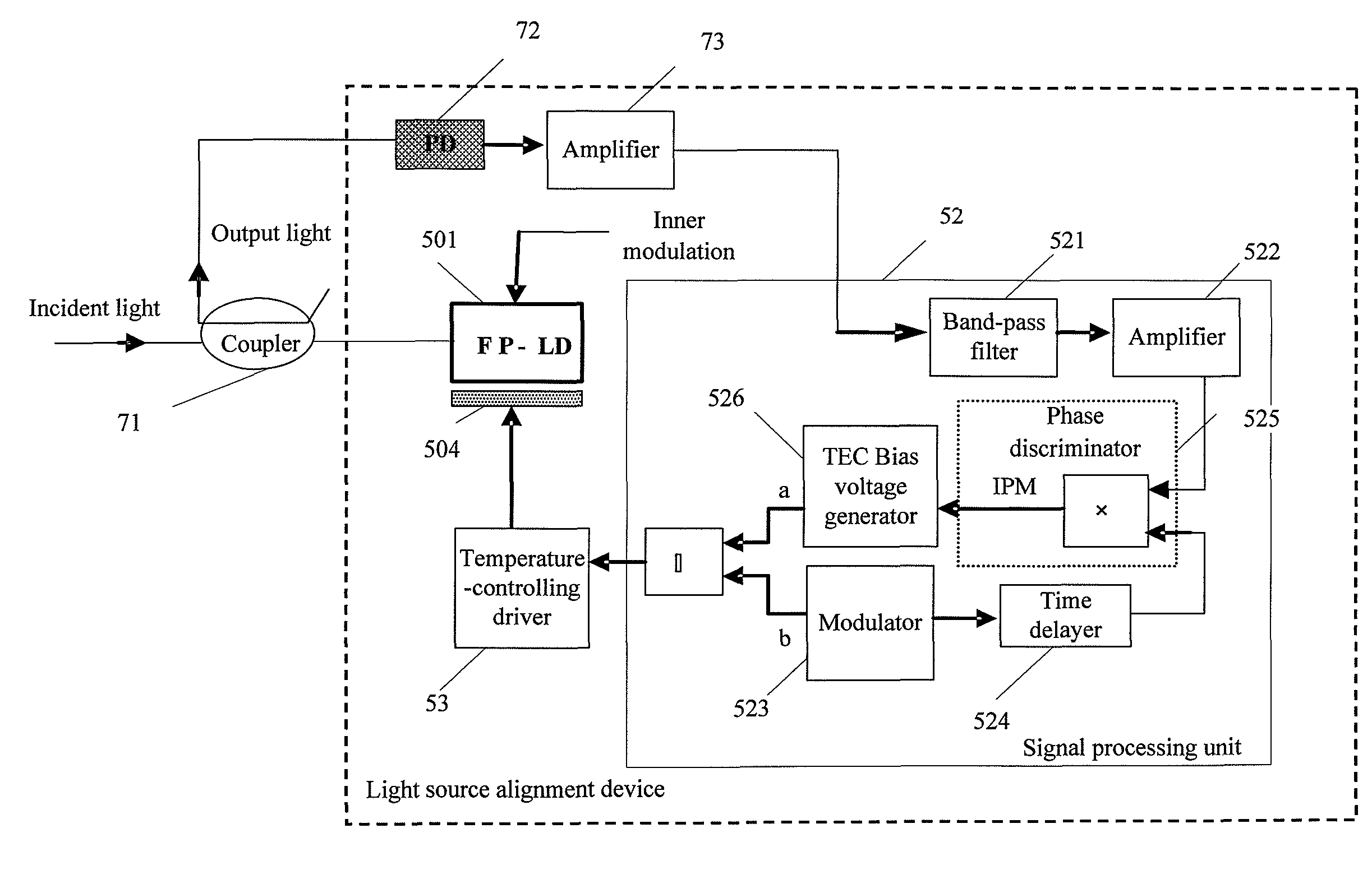
[0075]FIG. 7 is a structural view of a light source mode alignment device according to a third embodiment of the present disclosure.

[0076]Unlike the embodiment shown in FIG. 5, the incident light in this embodiment enters an FP-LD via a coupler 71 instead of a circulator. On one hand, the coupler 71 imports the incident light into the FP-LD in a proportion (for example, 50%), and on the other hand, the coupler 71 exports the output light of the FP-LD in a proportion for making a detection about an output optical power.

[0077]In this embodiment, a PD disposed at an exterior of the laser is employed. As shown in FIG. 7, the optical power of the light exported by the coupler 71 is detected by a PD 72. The PD 72 converts the optical power of the light exported by the coupler 71 into a current signal and sends the current signal to an amplifier 73 connected to the PD 72. A transimpedance amplifier inside the amplifier 73 a...


PUM


Abstract

A light source mode alignment device and method and a passive optical network system are provided. The device includes a laser and a temperature control unit connected to each other and further includes a signal processing unit. The laser converts an incident light into a current signal. The current signal is amplified and converted into a voltage signal via a transimpedance amplifier. Together with a modulation signal generated by the signal processing unit, the voltage signal adjusts a bias voltage of the temperature control unit.

Description

CROSS REFERENCE TO RELATED APPLICATIONS[0001]The application is a continuation-in-part application of PCT / CN2007 / 070398, filed on Aug. 1, 2007, which claims the benefit of priority to Chinese Patent Application No. 200610062091.7, entitled “Light Source Self-adapting Mode Alignment Device and Method” and filed on Aug. 10, 2006, both of which are incorporated herein by reference in their entirety.FIELD OF THE TECHNOLOGY[0002]The present disclosure relates to the field of optical communication, and more particularly to a light source mode alignment device, a light source mode alignment method, and a passive optical network system.BACKGROUND OF THE DISCLOSURE[0003]Currently, with the rapid development of video services, subscribers have an increasingly high demand for the bandwidth. Although the 2 Mbps bandwidth of a digital subscriber line (DSL) is sufficient for the current data transmission services, it is difficult to satisfy the video services. A new broadband access network, such...

Claims


Application Information

Patent Timeline
Patent Type & Authority Patents(United States)
IPC IPC(8): H01S3/10H04B10/572
CPCH04B10/572H04J14/02H04J14/025H04J14/0282H04J14/0246G02F2201/58H04J14/0226
Inventor ZHANG, XULIANGZHAO, JUNJIANG, TAOHUANG, WEILIN, HUAFENGWANG, YUNTAOWEI, GUOCHEN, JUNWANG, FENG
Owner HUAWEI TECH CO LTD
Why Eureka
Try Eureka