Combined type oscillation floater wave energy power generation device

A power generation device and combined technology, applied in ocean energy power generation, engine components, machines/engines, etc., can solve problems such as failure of hydraulic transmission mechanism, easy displacement of piston rod, unstable output power, etc., and achieve fewer moving parts , Superior follow-up performance and stable output power

Active Publication Date: 2014-07-23
OCEAN UNIV OF CHINA
View PDF10 Cites 16 Cited by
  • Summary
  • Abstract
  • Description
  • Claims
  • Application Information

AI Technical Summary

Problems solved by technology

[0003] In the above application, although a guide device is also installed on the buoy, in the actual sea trial process, it is found that under the impact of a relatively large wave, the buoy will still deviate significantly
In addition, because the hydraulic transmission mechanism is exposed on the outermost side of the fixed frame, it is directly impacted by the waves, and the piston rod is prone to deviation when moving, which will lead to failure or damage of the hydraulic transmission mechanism, and the output power is very unstable.

Method used


Image

  • Combined type oscillation floater wave energy power generation device
  • Combined type oscillation floater wave energy power generation device
  • Combined type oscillation floater wave energy power generation device

Examples


Embodiment 1

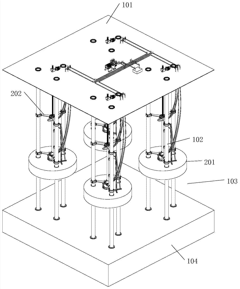
[0026] like Figure 1-Figure 5 Shown: The invention includes power generation systems and stationary systems.

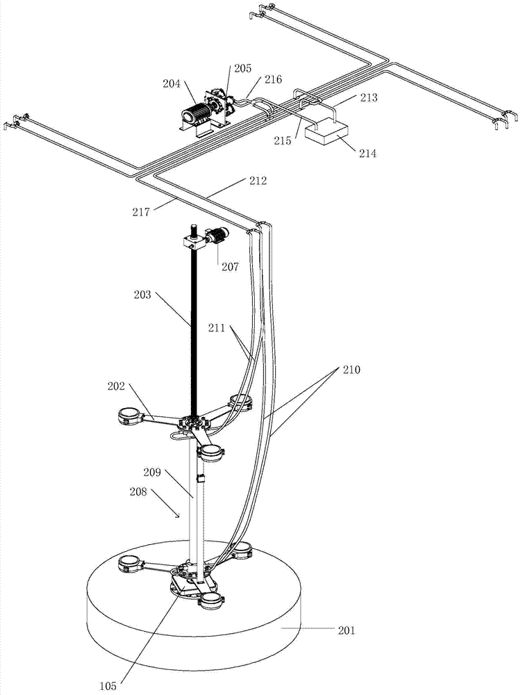
[0027] Wherein, the fixing system includes a submersible buoyant body 104 and a fixed frame 103 , the fixed frame 103 is fixedly connected to the top of the submerged buoyant body 104 , and a working platform 101 is arranged on the top of the fixed frame 103 . The power generation system includes a float 201 , an energy conversion device and a generator 204 . The float 201 is arranged on the four corners of the fixed frame 103. Each corner of the fixed frame 103 is provided with three guide rods 102 which are movably connected with the float 201. The float 201 is set on the guide rod 102 and moves up and down along the guide rod 102. The three guide rods 102 are positive Triangular arrangement. The energy conversion device includes a hydraulic motor 205 and four sets of identical hydraulic transmission mechanisms respectively arranged between the three guide rods 1...

Embodiment 2

[0034] Except following difference, other is with embodiment 1.

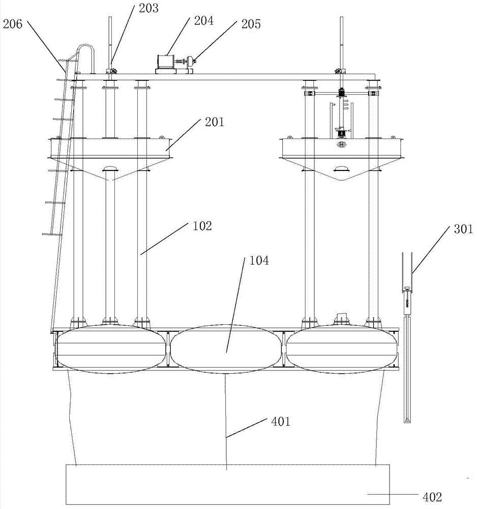
[0035] like figure 2 and Figure 4 As shown, the present invention includes a tidal level monitoring and self-adaptive system, the system includes a tide well 301 and a screw jack 203, the tide well 301 is fixedly connected with the tripod 202 of the hydraulic cylinder 208 through a support 302, and the screw jack 203 is connected to the hydraulic cylinder 208. Cylinder 208 is fixedly connected, and controls hydraulic cylinder 208 to lift. A liquid level switch 303 is provided in the tide well 301 , and the liquid level switch 303 is electrically connected to the starting motor 207 of the screw jack 203 . The starting motor 207 of the screw jack 203 is disposed on the working platform 101 .

Embodiment 3

[0037] Except following difference, other is with embodiment 1.

[0038] like figure 2 As shown, the present invention includes an anchoring system, which includes a counterweight 402 and an anchor cable 401 connected to the submersible body 104 .


PUM


Abstract

The invention relates to a combined type oscillation floater wave energy power generation device which comprises a power generation system and a fixing system. The fixing system comprises a snorkeling body, a fixing frame and a working platform, wherein the fixing frame is fixedly connected to the top of the snorkeling body, and the working platform is arranged on the top of the fixing frame. The power generation system comprises floaters, a hydraulic motor and four identical hydraulic transmission mechanisms and an electric generator, wherein each hydraulic transmission mechanism is arranged among three guide rods on each corner of the fixing frame. The floaters are arranged on the four corners of the fixing frame, each corner of the fixing frame is provided with three guide rods to be movably connected with the corresponding floater, and the guide rods are sleeved with the floaters. The hydraulic motor is arranged on the working platform. Each hydraulic transmission mechanism comprises a hydraulic cylinder, an oil pipe and an oil tank, wherein the hydraulic cylinder is located above the corresponding floater, the sleeve end of the hydraulic cylinder is fixedly connected to the corresponding three guide rods through a triangular frame, and a piston rod of the hydraulic cylinder is fixedly connected with the corresponding floater through a fixing disc. The combined type oscillation floater wave energy power generation device can output relatively-stable electric energy and is slightly affected by wave impact.

Description

technical field [0001] The invention belongs to the technical field of marine renewable energy utilization, and in particular relates to a combined oscillating float wave energy generating device. Background technique [0002] Chinese patent application CN103061962A discloses a hydraulic combined oscillating float wave energy generating device. The fixed frame is a cube structure, and the four corners of the fixed frame are respectively provided with columns. The mechanisms are respectively set on the four corner columns on the side of the fixed frame. The mixing tank and the hydraulic motor are set on the beam of the fixed frame. The hydraulic transmission mechanism includes a hydraulic cylinder. There is a hydraulic cylinder on the four sides of each column. Above, the sleeve end is fixedly connected to the column, and the piston rod is fixedly connected to the float through the support frame of the guide device. [0003] In the above application, although a guide device ...

Claims


Application Information

Patent Timeline
Patent Type & Authority Applications(China)
IPC IPC(8): F03B13/22
CPCY02E10/30
Inventor 史宏达刘臻郭广龙宋文杰刘鹏黎明赵环宇曹飞飞曲娜吕小龙朱凯
Owner OCEAN UNIV OF CHINA
Why Eureka
Try Eureka