System and method for dynamic range extension and stable low power operation of optical amplifiers using pump laser pulse modulation

a technology of dynamic range extension and low power operation, applied in the field of fiberoptic communication networks, can solve the problems of limiting the stability of the pump and the amplifier under low power operation, pump laser to pump laser to either drop below threshold or change output mode, etc., to achieve stable output power for the amplifier and stable output

Active Publication Date: 2006-09-19
II VI DELAWARE INC
View PDF6 Cites 15 Cited by
  • Summary
  • Abstract
  • Description
  • Claims
  • Application Information

AI Technical Summary

Benefits of technology

[0007]In order to address the above-described need in the art, the present invention discloses a system and method for controlling an optical amplifier wherein a gain medium of the amplifier receives optical excitation from a pulse-width modulated pump source, the time interval and between successive controlled duration (or controlled width) pulses of the pump source being much less than the lifetime of the excited state of pumped ions, such as Erbium ions, within the gain medium. Because the pump laser, when it is outputting a pulse, always operates at a current that is above the threshold current and that is also above the critical current level associated with coherence collapse operation, the pump operates in the stable coherence collapse regime. The pulse width may be adjusted (i.e., modulated) so as to produce an average power that matches a predetermined set point. By pulsing the laser pump light source, mode hopping of the pump laser is avoided within fast cycles and is averaged between multiple cycles, thereby leading to a stable output power for the amplifier at any output power. As a result, the gain medium also produces a stable output.

Problems solved by technology

Unfortunately, when the set point is such that the pump laser is operated near its lasing threshold, reflections in the optical path (from anywhere between the pump and the gain medium) can cause drastic fluctuations in the pump operation.
When the pump laser is operated close to its threshold, such reflections and other perturbing effects may cause the pump laser to either drop below threshold or to change its output mode.
Such fluctuations cause undesirable wide excursions in the pump output power that limit the stability both the pump and the amplifier under low power operation.
Additionally, pump bistability may occur at currents significantly above threshold, once again limiting the stability and operation of the amplifier / pump.
The FBG designs for good power stability also typically require long fiber lengths and one or more FBGs in the fiber pigtail at one or more meters from the pump chip, both leading to higher cost.
Although the use of FBGs provides a stable wavelength of operation for the pump at high output powers, it, unfortunately, does not ensure pump power stability at very low power.
Unfortunately, however, designs for high power and / or operation over a wide temperature range (so-called “uncooled” pumps) both typically require extremely low laser front facet reflectivity.
Low laser facet reflectivity enhances undesirable low power bistability and compounds the design problem.
Further, FBG designs for stable power operation at the high power end of the pump operating range require the use of stronger gratings and lower front facet reflectivity, both situations detrimental for low power stabilization.
Finally, in an uncooled pump, it is not possible to maintain tight detuning ranges on the order of a few nm, when the native pump wavelength shifts by 25 nm or more.
Disadvantageously, this second conventional method of pump control does not improve pump stability at very low power (near threshold) and adds complexity of additional circuit management.

Method used


Image

  • System and method for dynamic range extension and stable low power operation of optical amplifiers using pump laser pulse modulation
  • System and method for dynamic range extension and stable low power operation of optical amplifiers using pump laser pulse modulation
  • System and method for dynamic range extension and stable low power operation of optical amplifiers using pump laser pulse modulation

Examples


Embodiment Construction

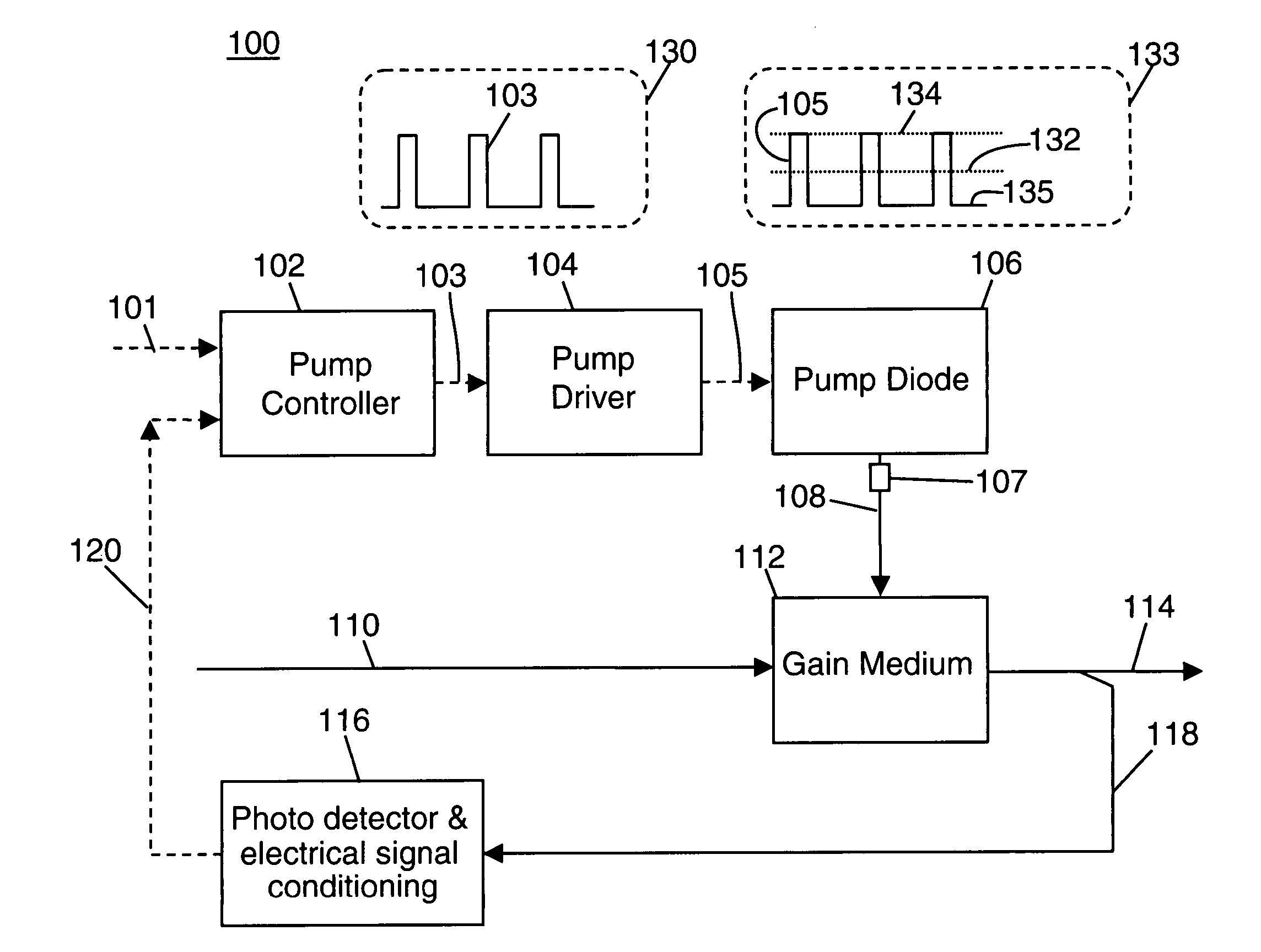
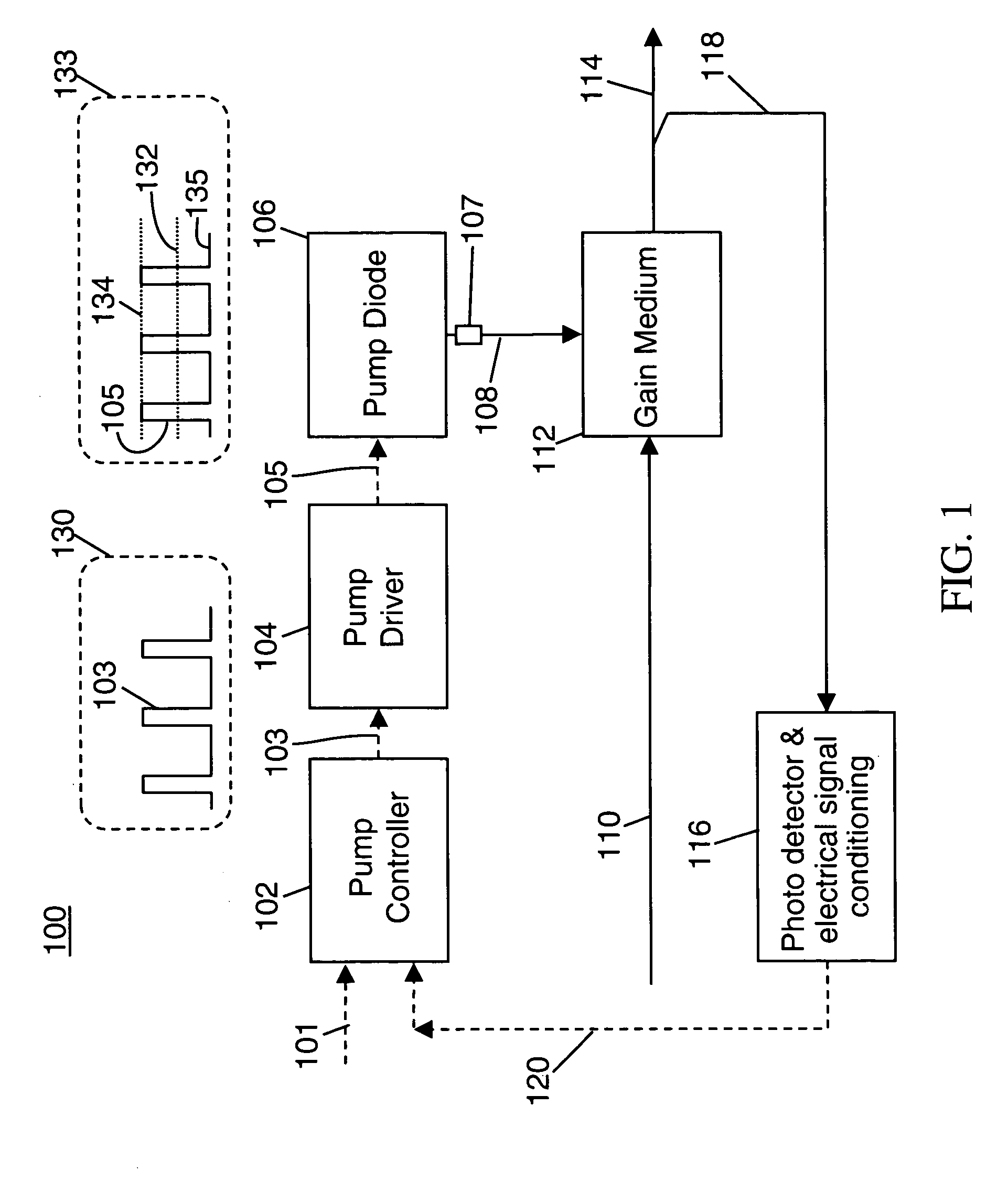
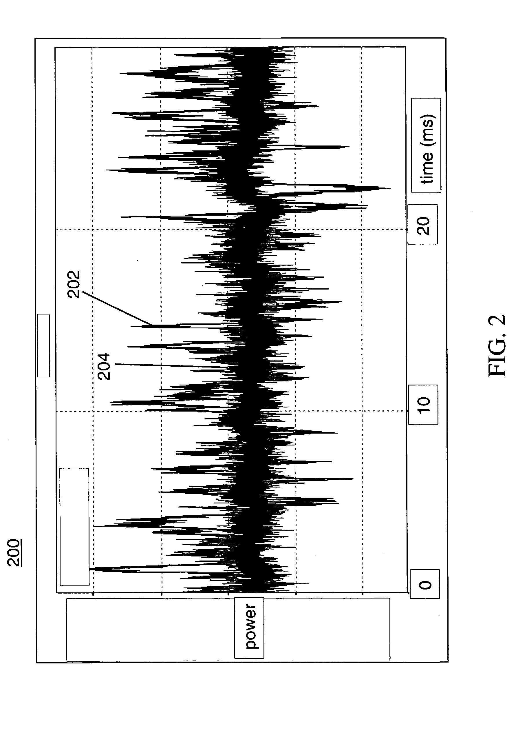
[0015]The present invention provides an improved system and method and for optical amplifier control within optical communications systems. The following description is presented to enable one ordinary skill in the art to make and use the invention and is provided in the context of a patent application and its requirements. Various modifications to the preferred embodiments will be readily apparent to those skilled in the art and the generic principles described herein may be applied to other embodiments. Thus, the present invention is not intended to be limited to the embodiments shown but is to be accorded the widest scope consistent with the principles and features described herein. In order to gain a detailed understanding of the invention, the reader is referred to the appended FIGS. 1–4 in conjunction with the following description. It is to be understood that the drawings are diagrammatic and schematic representations only and are neither limiting of the scope of the present ...


PUM


Abstract

An optical amplifier system comprises an optical gain medium receiving an input optical signal and outputting an amplified optical signal and a pump laser optically coupled to an input of the optical gain medium, wherein the pump laser emits a series of pulses to the optical gain medium, the pulses being emitted during coherence collapse operation of the pump laser, the time between pulses being shorter than an excited state lifetime of the optical gain medium.

Description

FIELD OF THE INVENTION[0001]The present invention relates to fiber-optic communications networks, and more particularly, to optical network equipment such as optical amplifiers in which pump powers are controlled to permit pumping under a wide dynamic power range and having stable operation at low pump powers.BACKGROUND OF THE INVENTION[0002]Optical Amplifiers, such as the well-known Erbium Doped amplifier, are pumped by a laser source, typically a laser diode, to derive signal gain. Conventional optical amplifier systems implement power control of the amplifier by changing the DC drive current applied to the pump laser diode so as to control the pump power supplied to a gain medium. This method is used to ensure that the optical amplifier operates at a certain power set point. Unfortunately, when the set point is such that the pump laser is operated near its lasing threshold, reflections in the optical path (from anywhere between the pump and the gain medium) can cause drastic fluc...

Claims


Application Information

Patent Timeline
Patent Type & Authority Patents(United States)
IPC IPC(8): H01S3/0941
CPCH01S3/06754H01S3/094003H01S5/0652H01S3/094076
Inventor GURUSAMI, ARAVANANPIKULA, DRAGANRICKETTS, DANIEL O.DAHL, SCOTT R.DAVIS, MONICA K.
Owner II VI DELAWARE INC
Why Eureka
Try Eureka