
Horn with acoustic cavity

A cavity and acoustic technology, applied in the direction of electrical components, loudspeakers, sensors, etc., can solve problems such as lack of sound quality, inability to distinguish music thickness and phase, and inability to achieve stereoscopic 3D effects, etc., to achieve clear phase directions thick time clear effect

Active Publication Date: 2017-10-20
深圳市金宏翔声学有限公司
View PDF6 Cites 5 Cited by
  • Summary
  • Abstract
  • Description
  • Claims
  • Application Information

AI Technical Summary

Problems solved by technology

The earphones in the prior art generally only install a speaker in the casing, and set one or two diaphragms that emit sound in the speaker, which cannot achieve the effect of noise reduction and vibration reduction. When the user plugs the earphone into the ear or When the ear is pulled out, the earphones will hear the noise from the sound film of the speaker; in addition, the sound of ordinary speakers on the market is 180° from the outside to the inside until it condenses into a point, and the condensing effect is evaluated The sound quality is good or bad, and the thickness and phase of the music cannot be distinguished
The stereoscopic 3D effect cannot be achieved, so the speakers in the prior art can no longer meet people's needs
Due to the ever-changing design of the acoustic cavity of the ear shell (that is, the cavity for the speaker) on the market, the cavity is rarely designed according to the acoustic principle, so it is difficult to achieve good sound quality.

Method used


Image

  • Horn with acoustic cavity
  • Horn with acoustic cavity
  • Horn with acoustic cavity

Examples


Embodiment Construction

[0028] In order to further explain the technical means and effects of the present invention to achieve the intended purpose of the invention, the specific implementation, structure, features and effects of the application according to the present invention will be described in detail below in conjunction with the accompanying drawings and preferred embodiments. . In the following description, different "one embodiment" or "embodiment" do not necessarily refer to the same embodiment. Furthermore, the particular features, structures, or characteristics of one or more embodiments may be combined in any suitable manner.

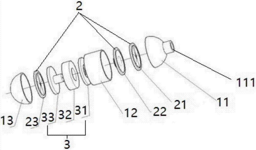
[0029] Such as figure 1 , figure 2 and image 3 As shown, an embodiment of the present invention provides a speaker with an acoustic cavity, which includes: a housing 1, a diaphragm assembly 2 and a magnetic circuit drive assembly 3, wherein

[0030] Housing 1, which includes a first cavity 11, a second cavity 12 and a third cavity 13, the first cavity 11, t...


PUM


Abstract

The invention discloses a horn with an acoustic cavity, relates to the technical field of electronic products and solves the problems that through the unique cavity structure design, a first 180-degree cavity and a second 180-degree cavity form a 360-degree space, the 360-degree space infinitely extends outwards from a central point to generate a 360-degree spatial sound sense, and a 3D stereoscopic space is really realized, so that a music source is clear, strong and definite in each phase position direction, and through the unique material and structure of two damping membranes, the noise and the reflection sound which are generated by a second vibrating diaphragm are eliminated to realize a noise reduction effect. The main technical scheme of the invention is as follows: the horn comprises a shell, a vibrating diaphragm component and a magnetic circuit driving component, wherein the shell comprises a first cavity, a second cavity and a third cavity, wherein the first cavity, the second cavity and the third cavity are connected in sequence; a vibrating diaphragm component comprises a first vibrating diaphragm arranged in a first cavity, a second vibrating diaphragm arranged in a second cavity and a third vibrating diaphragm arranged in a third cavity; and a magnetic circuit driving component is arranged in the second cavity and comprises a magnetic conducting plate, a magnet and a T iron. The horn is mainly used for the electronic products.

Description

technical field [0001] The invention relates to the technical field of electronic products, in particular to a speaker with an acoustic cavity. Background technique [0002] At present, earphones are often used in MP3 players, mobile phones, personal digital assistants (PDAs) or notebook computers, etc., as personal independent listening, making earphones one of the indispensable important accessories of electronic products nowadays. With the continuous improvement of people's requirements for sound quality, the sound quality effect of earphones has been paid more and more attention. The earphones in the prior art generally only install a speaker in the casing, and set one or two diaphragms that emit sound in the speaker, which cannot achieve the effect of noise reduction and vibration reduction. When the user plugs the earphone into the ear or When the ear is pulled out, the earphones will hear the noise of the sound film of the speaker; in addition, the sound of ordinary ...

Claims


Application Information

Patent Timeline
Patent Type & Authority Applications(China)
IPC IPC(8): H04R9/06H04R9/02
CPCH04R9/02H04R9/06H04R2400/11
Inventor 曹光荣
Owner 深圳市金宏翔声学有限公司
Learn More