

Hydraulic-pressure power device and pump thereof
A hydraulic power device and pump body technology, which is applied to liquid fuel engines, pumps, rotary piston type/oscillating piston type pump components, etc., can solve the problems of increasing the starting load of the motor, large starting load, and large motor loss
Patent Information
- Authority / Receiving Office
- CN · China
- Patent Type
- Applications(China)
- Current Assignee / Owner
- Publication Date
- 2017-10-24
Smart Images
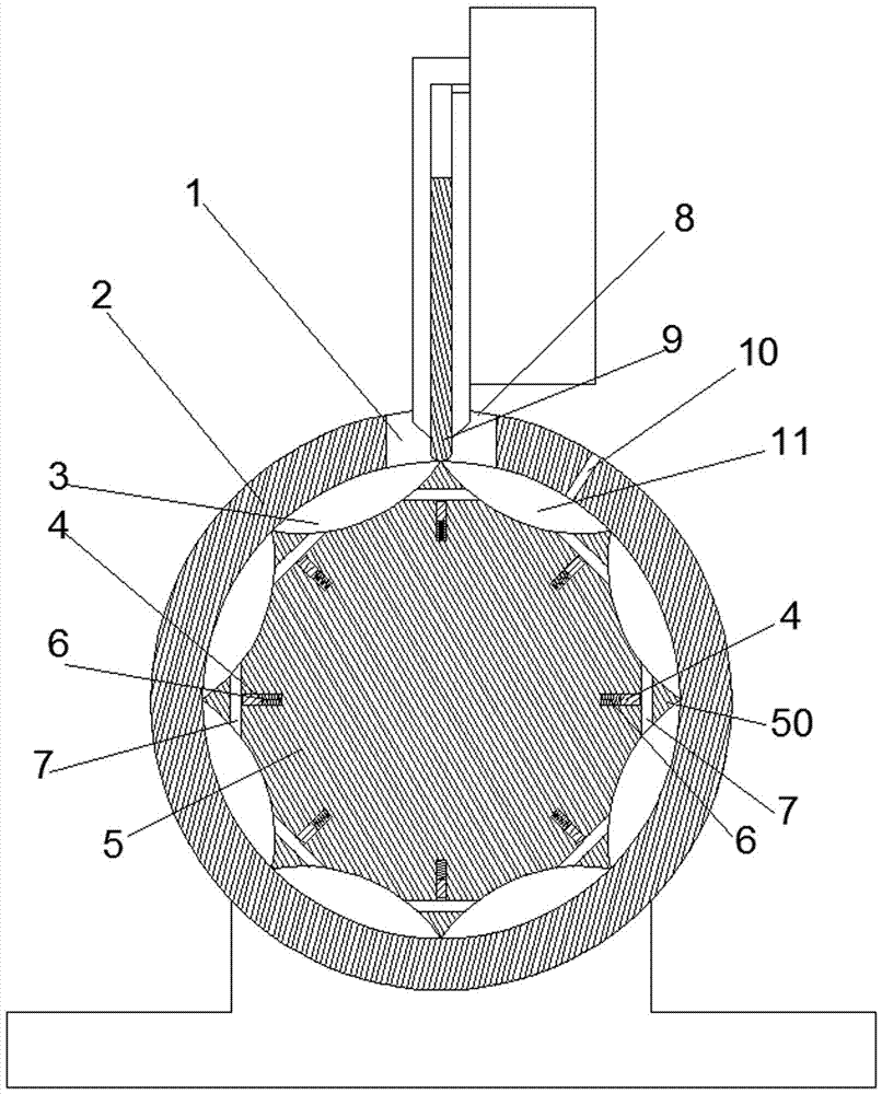
Figure 1 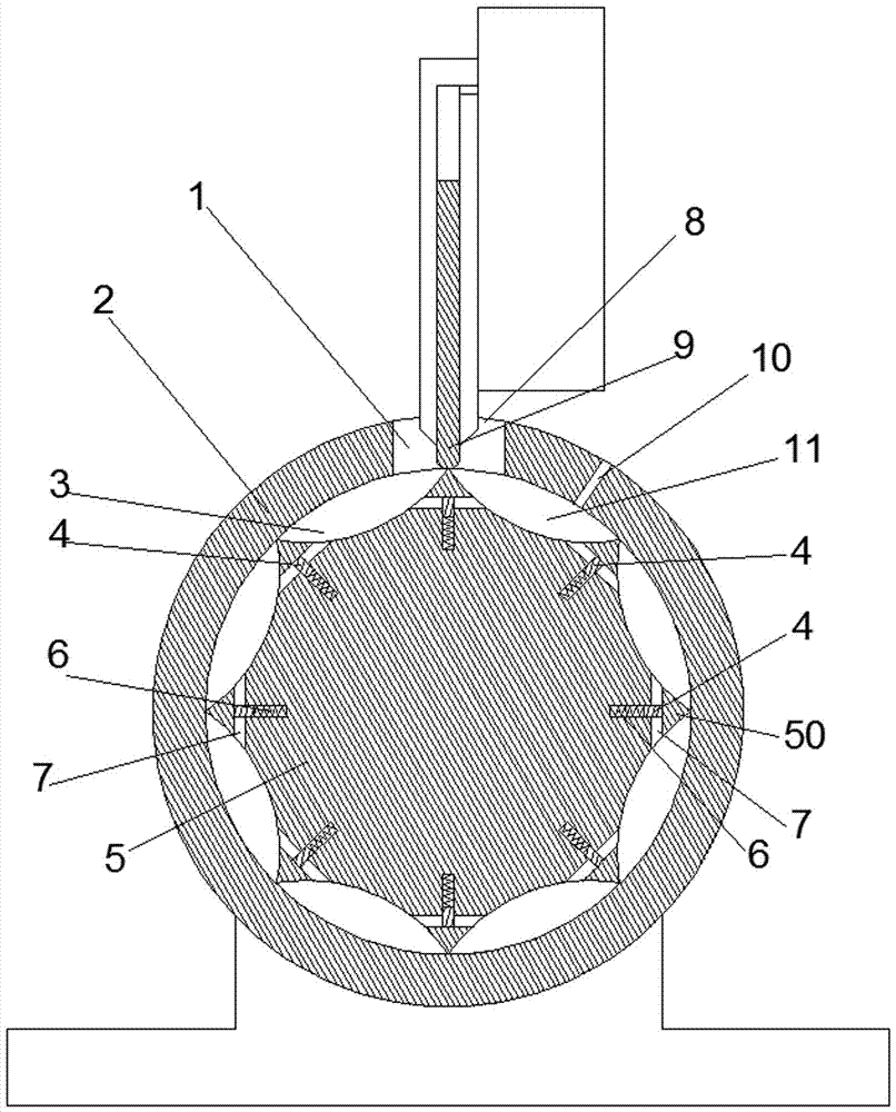
Figure 2 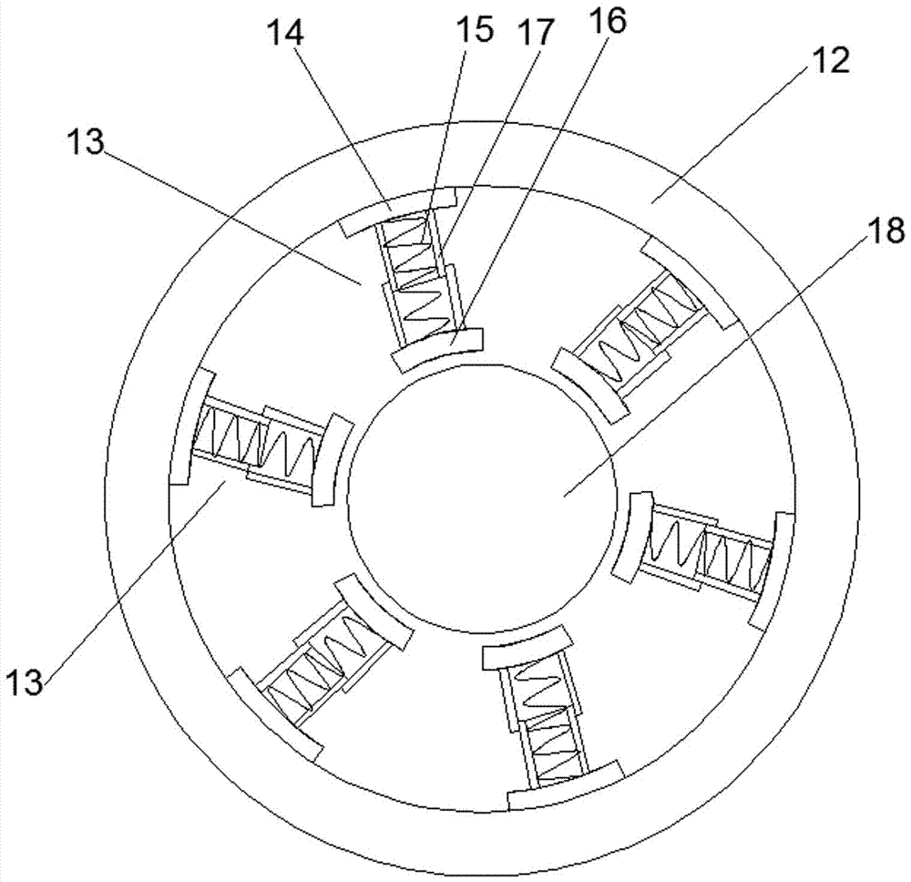
Figure 3
Abstract
Description
technical field
[0001] The invention relates to a hydraulic power device and its pump. Background technique
[0002] At present, hydraulic powertrains are relatively common in production and life. The hydraulic powertrain includes a motor and a pump driven by the motor. The existing pump is such as the "pump" disclosed in Chinese patent CN101749228A. A pump body is provided, and the pump body has a cylindrical hole inner cavity, and a rotor whose rotation axis extends along the front and rear directions is arranged in the cylindrical hole inner cavity. Shape-empty tangent. There is a hole on the outer periphery of the pump body, and a baffle is installed at the hole to guide and move. The baffle divides the hole into a liquid inlet and a liquid outlet. The rotor is a cylinder.
[0003] When in use, the rotor rotates clockwise, and the cavities on both sides of the rotor communicate with the liquid inlet and the liquid outlet respectively. The cavity connected with the liqu...
Examples
Embodiment Construction
[0019] Examples of hydraulic power units are Figure 1~7 Shown: comprise motor 37 and pump 36, and pump 36 comprises the pump body 2 that has cylindrical hole inner cavity, is provided with the rotor 5 that rotation axis extends along the front-back direction in pump body 2, and the cross-section of rotor is polygonal structure, and Each side is in a concave arc shape, and a convex rib 50 extending along the front and back directions that is tangent to the cylindrical hole is formed between two adjacent sides, and the pump body is provided with a liquid inlet hole separated by a partition 9 8 and the liquid outlet hole 1, the partition 9 can move back and forth along the radial direction of the rotor, and the inner end of the partition 9 is slidingly and push-fitting with the outer peripheral surface of the rotor 5 . Each rib 50 is provided with an oil guide channel 7 connecting both sides of the rib in the circumferential direction. The rotor is guided and moved along the rad...