Cut-off device for pipeline

A kind of interceptor and pipeline technology, applied in the direction of fluid distribution valve, sliding valve, functional valve type, etc., can solve the problems of loss, water overflow, safety accident economy, etc., to avoid safety accidents and waste of water resources, good prevention spillover effect

Pending Publication Date: 2017-10-24
刘建国
View PDF6 Cites 4 Cited by
  • Summary
  • Abstract
  • Description
  • Claims
  • Application Information

AI Technical Summary

Problems solved by technology

[0003] Although the existing pools are usually equipped with overflows, since the water flowing out of the faucet is sprayed under the action of the water supply pressure in the water pipe, its water injection speed is greater than the drainage speed of the overflow port, so

Method used


Image

  • Cut-off device for pipeline
  • Cut-off device for pipeline
  • Cut-off device for pipeline

Examples


Embodiment 1

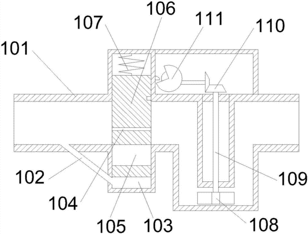
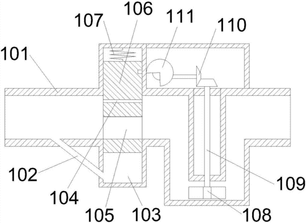
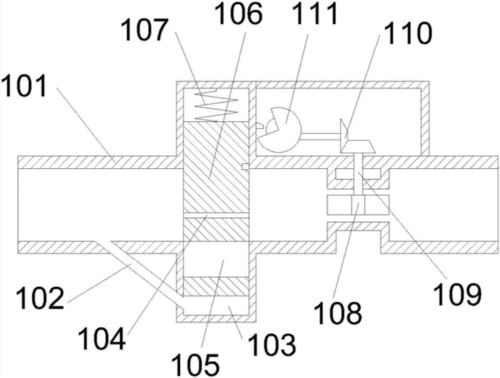
[0028] Such as figure 1 and figure 2 As shown, this embodiment provides a pipeline interceptor, which includes: a metering impeller, a control mechanism, and a stop piston arranged on the pipeline for controlling the opening / closing of the pipeline; the opposite sides of the pipeline are respectively provided with The first chamber and the second chamber, and the first chamber and the second chamber communicate with the pipeline; the outer wall of the stop piston is attached to the inner wall of the first chamber and the second chamber; the stop piston One end of the stop piston is set in the first chamber through the elastic reset mechanism; when the stop piston is in the closed state, the other end of the stop piston is located in the second chamber, and forms a pressure chamber with the inner side wall of the second chamber; the pressure chamber passes the pressure The return pipe communicates with the pipeline, and the connecting end of the pressure return pipe and the p...

Embodiment 2

[0041]This embodiment provides a pipeline interceptor, which includes: a metering impeller, a control mechanism, and a stop piston arranged on the pipeline for controlling the opening / closing of the pipeline; the opposite sides of the pipeline are respectively provided with first cavities chamber and the second chamber, and the first chamber and the second chamber are in communication with the pipeline; the outer wall of the stop piston is attached to the inner wall of the first chamber and the second chamber; one end of the stop piston passes through The elastic reset mechanism is set in the first chamber; when the stop piston is in the closed state, the other end of the stop piston is located in the second chamber, and forms a pressure chamber with the inner side wall of the second chamber; The pipeline is connected, and the connecting end of the pressure return pipe and the pipeline is located downstream of the stop piston.

[0042] Wherein, the stop piston is provided with...


PUM


Abstract

The invention relates to a cut-off device for a pipeline. The cut-off device comprises a metering impeller, a control mechanism and a stopping piston which is arranged on the pipeline and used for controlling the pipeline to be opened or closed; the two opposite sides of the pipeline are provided with a first cavity and a second cavity which communicate with the pipeline; one end of the stopping piston is arranged in the first cavity through an elastic reset mechanism; when the stopping piston is in a closed state, the other end of the stopping piston is located in the second cavity and forms a pressure chamber with the inner side wall of the second cavity; the pressure chamber communicates with the pipeline through a pressure backflow pipe, and the end, communicating with the pipeline, of the pressure backflow pipe is located on the down stream of the stopping piston; the metering impeller is arranged in the pipeline and located on the up stream of the stopping piston; the stopping piston is provided with a capillary hole and a through hole; and the side wall of the first cavity is provided with a limiting mechanism used for locking the stopping piston. According to the cut-off device for the pipeline, a good anti-overflow effect can be achieved, and safety accidents and water resource waste which are caused by the fact that a user forgets turning off a spigot are avoided.

Description

technical field [0001] The invention belongs to the technical field of pipeline interceptors, and in particular relates to a pipeline interceptor. Background technique [0002] The water pipes in existing households mainly control the on / off of the pipes through the faucet. When you forget to turn off the faucet, especially when you encounter a water outage, you forget to turn off the faucet after turning on the faucet and no water comes out. The faucet is open. [0003] Although the existing pools are usually equipped with overflows, since the water flowing out of the faucet is sprayed under the action of the water supply pressure in the water pipe, its water injection speed is greater than the drainage speed of the overflow port, so when it meets the water pipe When the road is blocked, if no one finds it in time, the tap that is forgotten to turn off will cause water to overflow from the pool, which will not only cause safety accidents and economic losses, but also cause...

Claims


Application Information

Patent Timeline
IPC IPC(8): F16K21/16F16K3/26
CPCF16K3/262F16K21/165
Inventor 刘建国
Owner 刘建国
Why Eureka
Try Eureka