Spliced wall brightness uniformity control system and control method thereof

A technology of brightness uniformity and control system, applied in the direction of instruments, static indicators, etc., can solve the problems of differences in brightness life of each module, batch difference of LED lights, LED lights, etc.

Active Publication Date: 2017-10-24
TCL CHINA STAR OPTOELECTRONICS TECH CO LTD
View PDF3 Cites 7 Cited by
  • Summary
  • Abstract
  • Description
  • Claims
  • Application Information

AI Technical Summary

Problems solved by technology

[0005] 1) In the entire splicing wall system, the temperature of each module is different, and the heat generated by the modules will accumulate upwards, causing the temperature of the modules stacked on the upper side of the splicing wall to be higher than the temperature of the modules on the lower side. The operating temperature of the LED light on the backlight panel will cause the brightness attenuation difference, such as figure 1 As shown in the LED lamp at different working ambient temperatures, the decay curve of brightness over time can be seen to have obvious differences.
[0006] 2) The difference in batches of LED lights in the backlight and the life span of LED lights from different suppliers may cause differences in the actual brightness life of each module
It can be clearly seen that under the same working conditions, LEDs from different suppliers have large differences in the degree of brightness attenuation over time.

Method used


Image

  • Spliced wall brightness uniformity control system and control method thereof
  • Spliced wall brightness uniformity control system and control method thereof
  • Spliced wall brightness uniformity control system and control method thereof

Examples


Embodiment

[0032] like Figure 4 As shown, a video wall brightness uniformity control system includes a light sensor 1 and a circuit control system. The light sensor 1 is connected to the circuit control system.

[0033] In this embodiment, the light sensors 1 are correspondingly arranged on the detection areas on the backlight panels 4 of the display screens.

[0034] One or more detection areas can be set on the backlight panel 4 of each display screen.

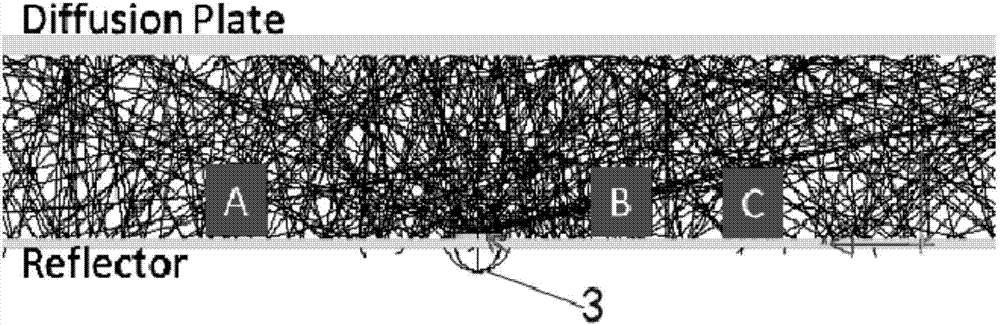
[0035] It should be noted that, if image 3 As shown, in the conventional backlight architecture, it can be found that the illuminance of certain positions is only related to the luminous intensity of the LED lamp 3 . It can be seen from the optical square software that after the optical structure is determined, although the light emitted by the LED lamp 3 passes through the diffuser plate and the reflector for many times, the illuminance of different specific positions on the reflector will be different, but for each fixed Positi...

Embodiment 2

[0047] like Image 6As shown, a control method of the video wall brightness uniformity control system includes the following steps.

[0048] Step S1) Acquiring a reference value for comparing the change of the actual light sensitivity value; in this step S1), the reference value is the light sensitivity value defined by the circuit control system.

[0049] Step S2) Obtain the actual light sensitivity value of each detection area.

[0050] Step S3) Calculate the absolute value of the difference between the actual light sensitivity value and the reference value: calculate and compare the actual light sensitivity value of each detection area with the reference value of the detection area to obtain the actual light sensitivity The absolute value of the difference between the value and the base value.

[0051] Step S4) judging whether the absolute value exceeds the set threshold, if so, define the detection area as a brightness adjustment area and enter step S5); if not, return t...


PUM


Abstract

The invention discloses a spliced wall brightness uniformity control system comprising light inductors and a circuit control system. The light inductors are correspondingly arranged in all the detection areas of all the display screen backlight boards. The light inductors are used for detecting the actual light perception value of the corresponding detection areas in real time. The light inductors are connected with the circuit control system. The circuit control system is used for acquiring a reference value used for comparing the change of the actual light perception value and acquiring the actual light perception value from the light inductors and comparing the reference value and the actual light perception value. When the absolute value of the difference value of the actual light perception value of a certain detection area and the reference value exceeds the threshold, the circuit control system is used for controlling the driving conditions of the LED lamps on the backlight boards so that the brightness of the detection area is maintained to be uniform to that of other detection areas. The invention also discloses a control method of the spliced wall brightness uniformity control system.

Description

technical field [0001] The invention relates to the fields of splicing walls and the like, in particular to a splicing wall brightness uniformity control system and a control method thereof. Background technique [0002] With the continuous development of the display technology, the application occasions of the display are more and more extensive. Not only for TV, monitor, industrial display, medical display, but also more and more used in public display occasions. In public display applications, it is generally required that the display has a larger display area to meet the requirements of people watching from a long distance and displaying a large amount of information. However, as far as the development status of LCD TV monitors is concerned, the conventional size ranges from 32 inches to 55 inches. If displays in this size range are used for public display, multi-screen splicing is required. [0003] The splicing wall is composed of multiple display screens, usually th...

Claims


Application Information

Patent Timeline
Patent Type & Authority Applications(China)
IPC IPC(8): G09G3/34
CPCG09G3/3406G09G3/3413G09G2320/0233
Inventor 苏赞加
Owner TCL CHINA STAR OPTOELECTRONICS TECH CO LTD
Why Eureka
Try Eureka