Loudspeaker box cavity and loudspeaker box possessing the loudspeaker box cavity

A speaker and cavity technology, applied in frequency/direction characteristic devices, transducer shells/cabinets/brackets, sensors, etc., can solve problems such as speaker sound entering, affecting microphone pickup hole to pick up user voice, etc.

Active Publication Date: 2017-10-24
BEIJING JINGDONG SHANGKE INFORMATION TECH CO LTD +1
View PDF5 Cites 5 Cited by
  • Summary
  • Abstract
  • Description
  • Claims
  • Application Information

AI Technical Summary

Problems solved by technology

[0005] In order to solve the above-mentioned problems in the prior art, that is, in order to solve the problem that the sound of the speaker enters the microphone area, which seriously affects the microphone sound pickup hole to pick up the user's voice, the embodiment of the present invention provides a speaker cavity a

Method used


Image

  • Loudspeaker box cavity and loudspeaker box possessing the loudspeaker box cavity
  • Loudspeaker box cavity and loudspeaker box possessing the loudspeaker box cavity
  • Loudspeaker box cavity and loudspeaker box possessing the loudspeaker box cavity

Examples


Embodiment Construction

[0039] Preferred embodiments of the present invention are described below with reference to the accompanying drawings. Those skilled in the art should understand that these embodiments are only used to explain the technical principles of the present invention, and are not intended to limit the protection scope of the present invention.

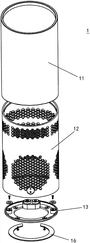
[0040] According to one aspect of the present invention, the present invention relates to a cloth mesh cylinder for a sound box.

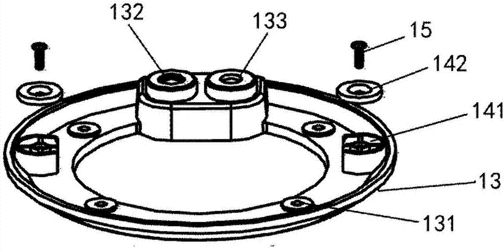
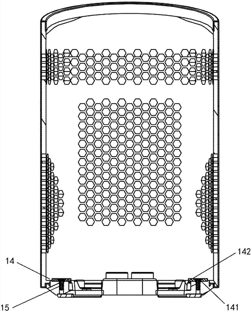
[0041] According to the overall inventive concept of the cloth mesh cylinder in one embodiment of the present invention, the cloth mesh cylinder for sound boxes in one embodiment of the present invention includes: cloth mesh, cylindrical support frame, bottom shell and suction part, wherein the cloth mesh covers On the cylindrical support frame, the bottom case is arranged on the bottom of the cylindrical support frame, the suction part is arranged inside the bottom case, and the bottom case is fixed on the speaker...


PUM


Abstract

The invention relates to a loudspeaker box cavity and a loudspeaker box. The loudspeaker box cavity and the loudspeaker box are used to solve a problem that a loudspeaker sound penetrates into a microphone area so that a process that a user sound is picked by a microphone pickup hole is severely influenced. The loudspeaker box cavity comprises a first shell and a second shell, wherein the first shell is provided with at least one first opening used for installing a loudspeaker; the first shell and the second shell are assembled together to form a first internal space; at least one closed chamber is formed in walls of the first shell and the second shell and the walls surround the first internal space; and the closed chamber is used to block a sound wave which is generated from the loudspeaker and is transmitted to a microphone installed on an outer side of the second shell or the microphone pickup hole from the loudspeaker along materials themselves of the first shell and the second shell. At least one sound insulation cavity is arranged on a shell between the first shell and the second shell of the loudspeaker box cavity so as to block a sound of the loudspeaker to be transmitted to the microphone area through the shell materials themselves so that a space nearby the microphone has a good acoustics environment.

Description

technical field [0001] Embodiments of the present invention relate to a sound box cavity and a sound box with the sound box cavity. Background technique [0002] Nowadays, speakers are generally equipped with microphones. With the development of information technology, people are choosing smart speakers more and more, and the power of the selected smart speakers is increasing, causing the sound of the speaker to spread to the microphone through the shell material itself surrounding the speaker installation cavity and the surrounding air The pickup hole seriously interferes with the microphone pickup hole picking up the user's voice. [0003] In order to solve this problem, the traditional approach is often to increase the distance between the speaker and the microphone pickup hole. However, this approach leads to an increase in the volume of the sound box and an increase in the materials used, which in turn leads to an increase in the manufacturing cost of the sound box. ...

Claims


Application Information

Patent Timeline
IPC IPC(8): H04R1/28H04R1/02
CPCH04R1/02H04R1/2888
Inventor 张猛
Owner BEIJING JINGDONG SHANGKE INFORMATION TECH CO LTD
Why Eureka
Try Eureka