Magnetic-force separation equipment

A technology of magnetic separation and equipment, applied in metal processing equipment, pile separation, object separation, etc., can solve the problems of reducing production efficiency, wasting manpower, reducing work efficiency, etc., to achieve fast and efficient operation, improve efficiency, and quickly leveling Effect

Active Publication Date: 2017-10-27
JINAN AOTTO TECH
View PDF6 Cites 0 Cited by
  • Summary
  • Abstract
  • Description
  • Claims
  • Application Information

AI Technical Summary

Problems solved by technology

However, since the sheet is easily oxidized during transportation and storage, in order to avoid oxidation of the sheet, the sheet must be coated with anti-rust oil before leaving the factory.
Sheets coated with anti-rust oil will cause stickiness between the sheets when they are stacked, which is not conducive to the separation of the sheets, resulting in the inability of the end suction cup of the robot or manipulator to accurately absorb the single sheet, resulting in an automatic loading and unloading production line. It cannot work normally, which reduces the work efficiency and loses the advantages of the automatic loading and unloading production line
[0004] At the same time, due to the extremely limited working space in the stamping automatic loading and unloading system, the sizes of the sheets are not the same. Even if some stamping automatic loading and unloading systems have a magnetic spreader, it needs to be manually adjusted according to the size of the stamping workpiece sheet. Manual adjustment reduces production efficiency and wastes manpower

Method used


Image

  • Magnetic-force separation equipment
  • Magnetic-force separation equipment
  • Magnetic-force separation equipment

Examples


Embodiment Construction

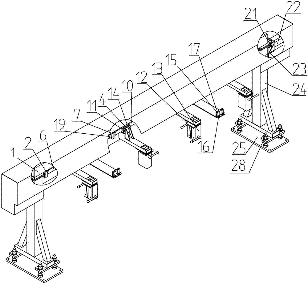
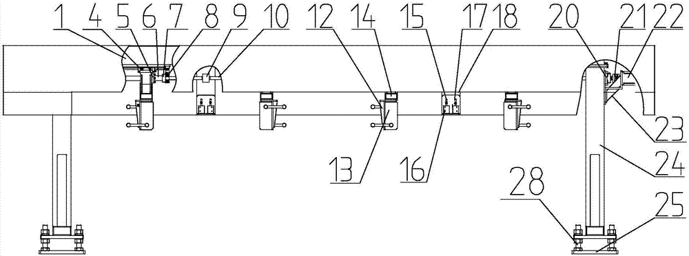
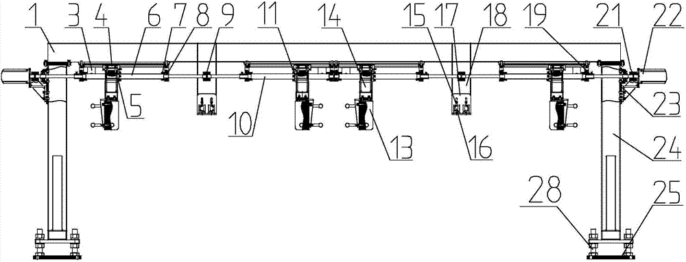
[0031] according to Figure 1 to Figure 10 As shown, a magnetic splitting device includes a bracket structure and a beam structure supported on the bracket structure, and also includes a transmission mechanism, a magnetic splitting structure, a detection structure and a driving structure. The transmission mechanism is provided with two sets, two sets The transmission mechanism can separate two stacks of sheets at the same time. The transmission mechanism includes screw mounting base 2, left-handed screw 6, left-handed screw 5, right-handed screw 10, right-handed screw 11 and coupling 9 , the left-handed screw 6 and the right-handed screw 10 are installed on the beam structure through the screw mounting base 2, the left-handed screw nut 5 and the right-handed screw nut 11 are respectively connected with the left-handed screw 6 and the right-handed screw 10, and the left-handed screw The rod 6 and the right-handed screw 10 are connected by a coupling-9, and the screw mounts 2 ar...


PUM


Abstract

The invention discloses magnetic-force separation equipment which comprises transmission mechanisms, magnetic-force separation structures, a detection structure and a drive structure. Each transmission mechanism comprises screw mounting seats, a left-handed screw, a left-handed nut, a right-handed screw, a right-handed nut and a first coupler; the magnetic-force separation structures are symmetrically distributed, each magnetic-force separation structure mainly comprises a magnetic-force separator, a mounting support and a connecting frame; the detection structure mainly comprises a self-reflecting photoelectric switch, a rotary mounting seat, an L-shaped connecting plate and a mounting rectangular tube, the mounting rectangular tube is mounted on a cross beam structure, the drive structure mainly comprises a second coupler, a servo motor and a motor mounting seat, and the motor mounting seat is fixed on a support structure. The magnetic-force separation equipment has the advantages that feeding and exiting of the magnetic-force separator can be adjusted according to the size of plate materials, single piece of the plate material is detected accurately, piles of plate materials can be separated, and high efficiency and high accuracy are achieved.

Description

technical field [0001] The invention relates to the technical field of sheet material splitting, in particular to a magnetic splitting device. Background technique [0002] In the machinery manufacturing industry, when the sheets are cold stamped, each layer of sheets must be separated. Especially in the stamping production of auto parts, an automatic loading and unloading system is currently used, and an industrial joint robot or manipulator is used to drive the end suction cup. The workpiece is sucked into the next process for stamping. [0003] In the machinery manufacturing industry, the separation of plates during cold stamping operations, especially in stamping plants for automobile production, uses robotic automated production lines to separate plates. Since robots grab materials instead of manual loading, the plates are directly picked up by the suction cup on the robot arm. After sucking up, put it into the next process to form. However, since the sheet metal is e...

Claims


Application Information

Patent Timeline
IPC IPC(8): B21D43/24B21D43/18B21C51/00B65H3/16
Inventor 苗金钟孟昭靖王昌杰
Owner JINAN AOTTO TECH
Why Eureka
Try Eureka