Preliminary Positioning Method of Tire Pressure Monitoring System

A tire pressure monitoring system and preliminary positioning technology, applied in tire measurement, tire parts, vehicle components, etc., can solve problems such as security loopholes, loss of practical benefits, and inability to replace tire pressure detectors by themselves

Active Publication Date: 2019-10-01
ORANGE ELECTRONICS
View PDF6 Cites 0 Cited by
  • Summary
  • Abstract
  • Description
  • Claims
  • Application Information

AI Technical Summary

Problems solved by technology

[0004] However, when the user wants to replace the tire pressure detector, he must first read the codes of each tire pressure detector, and then input the old codes to the new tire pressure detector one by one to correspond to the tire pressure. To detect the codes of the tires at each position built in the system, the aforementioned cumbersome steps must be performed by professional computer software, so ordinary car owners cannot replace the tire pressure detectors by themselves. For this reason, the industry has developed a A tire pressure detection system that can identify the position of each tire pressure detector without the need for the original tire pressure detector code;
[0005] However, the aforementioned tire pressure detection system often needs to spend a period of time (generally 20 minutes) to determine the position of each tire pressure detector when distinguishing the position of each tire pressure detector, so that the tire pressure monitoring will appear The empty window period creates a safety loophole. What’s more, in many cases, the driver only needs to move for a short distance. Therefore, before the tire pressure detection system judges the correct position of each tire pressure detector, the user has reached In this way, the tire pressure monitoring system will lose its practical benefits, so a preliminary positioning method for the tire pressure monitoring system is needed

Method used


Image

  • Preliminary Positioning Method of Tire Pressure Monitoring System
  • Preliminary Positioning Method of Tire Pressure Monitoring System
  • Preliminary Positioning Method of Tire Pressure Monitoring System

Examples


Embodiment Construction

[0026] The technical solutions of the present invention will be clearly and completely described below in conjunction with the accompanying drawings. Apparently, the described embodiments are part of the embodiments of the present invention, not all of them. Based on the embodiments of the present invention, all other embodiments obtained by persons of ordinary skill in the art without making creative efforts belong to the protection scope of the present invention.

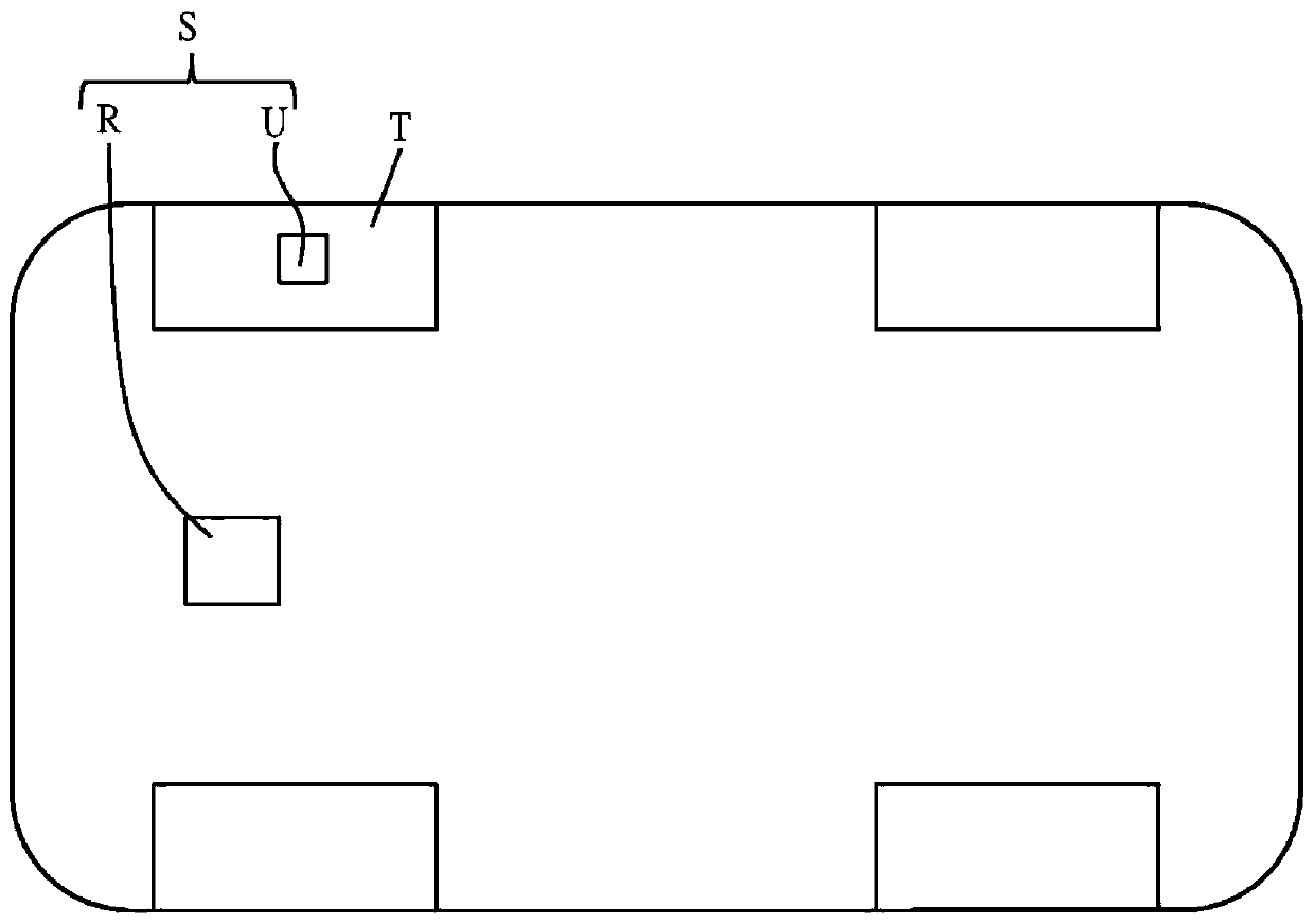
[0027] The method of the present invention is applied to a tire pressure monitoring system (Tire Pressure Monitoring System, TPMS). see figure 1 , the tire pressure monitoring system S includes a receiver R and a plurality of monitors U. The monitors U are respectively installed on the four wheels T of the vehicle (including two front wheels T and two rear wheels T), and each monitor U has a sensing device and a signal transmission device respectively. The sensing device can detect data such as tire pressure and...


PUM


Abstract

The invention provides a primary localization method for a tire pressure monitoring system. The primary localization method mainly comprises the following steps: receiving a tire pressure signal by a receiver and capturing an identifier therein, then comparing the captured identifier with corresponding identifiers in the database, if comparison result is the same, setting the captured identifier as one known identifier, repeating the process until the identifiers of all the received tire pressure signals are compared respectively, and pointing each known identifier to a specific wheel according to one pointer of the corresponding tire pressure signal when the quantity of the known identifiers is equal to the quality of a monitor, so that the effect of realizing the primary localization in short time is achieved.

Description

technical field [0001] The invention relates to a wireless tire pressure detection method, in particular to a preliminary positioning method of a tire pressure monitoring system. Background technique [0002] In recent years, cases of car accidents caused by abnormal tire pressure or blown tires are common, so countries around the world are actively implementing relevant laws, and car tire pressure detection systems have become the basic equipment for new cars in Europe and the United States. The tire pressure detection system has four tire pressure detectors and receivers, each tire pressure detector is installed on each tire, and each tire pressure detector will return the tire pressure signal at a certain interval of time To the receiver, and then display the tire pressure value of each tire through the display, if the value sensed by any tire pressure detector is abnormal, an alarm signal will be generated; [0003] In order to distinguish whether each tire pressure det...

Claims


Application Information

Patent Timeline
Patent Type & Authority Patents(China)
IPC IPC(8): B60C23/04
Inventor 游鸿志苏佳聪吴锡文
Owner ORANGE ELECTRONICS
Why Eureka
Try Eureka