Check patentability & draft patents in minutes with Patsnap Eureka AI!

Workpiece detection equipment

A workpiece detection and equipment technology, applied in the field of machinery, can solve the problem of high labor costs and achieve the effect of reducing labor costs

Inactive Publication Date: 2017-11-03
DONGGUAN UESTC PRECISION AUTOMATION
View PDF0 Cites 0 Cited by
  • Summary
  • Abstract
  • Description
  • Claims
  • Application Information

AI Technical Summary

Problems solved by technology

At present, the pallets are generally put on the conveyor belt, and then the pallets are transported to the designated position through the conveyor belt, and then the packing boxes are stacked on the pallets layer by layer, and the process of putting the pallets on the conveyor belt is currently done by Manually hug the pallets and then move them to the conveyor belt, the labor cost is high

Method used


Image

  • Workpiece detection equipment
  • Workpiece detection equipment
  • Workpiece detection equipment

Examples


Embodiment Construction

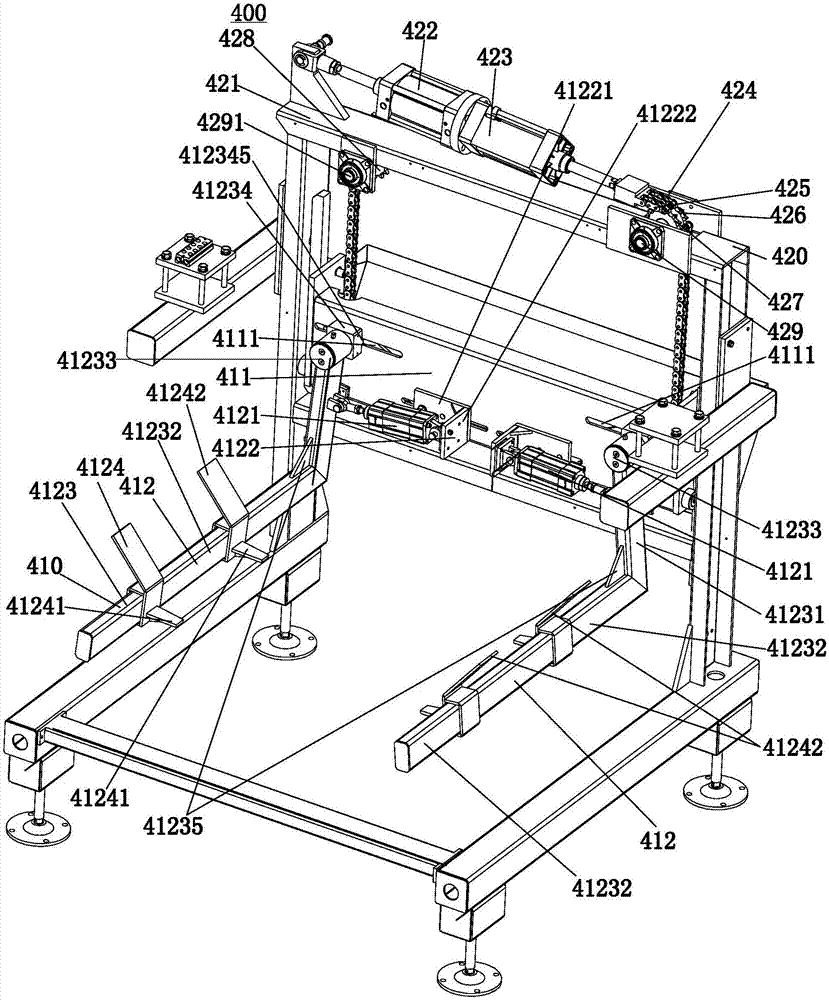
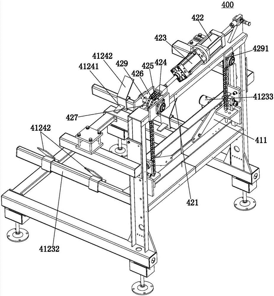
[0013] reference Figure 1 to Figure 3 The workpiece detection equipment 410 of the present invention includes a supporting back plate 411 and two plug-in arm assemblies 412 symmetrically connected to both sides of the front wall of the supporting back 411.

[0014] The plug-in arm assembly 412 includes a plug-in cylinder 4121, a plug-in cylinder base 4122, a plug-in arm 4123, and at least two plug-in kits 4124. The plug-in cylinder base 4122 includes a vertical fixing plate 41221 and a cylinder mounting plate 41222 extending vertically forward from the inner end of the vertical fixing plate 41221. The vertical fixing plate 41221 is fixed to the front side wall of the supporting back plate 411. The fixed end of the plug-in cylinder 4121 is fixedly connected to the cylinder mounting plate 41222 against a side wall of the vertical fixing plate 41221. The supporting back plate 411 is provided with a horizontal sliding groove 4111 above the outer side of the plug-in cylinder 4121. ...


PUM


Abstract

The invention discloses a plug-in cylinder seat of workpiece detection equipment, which comprises a vertical fixing plate and a cylinder mounting plate vertically extending forward from the inner end of the vertical fixing plate. The fixed end of the cylinder is fixed to the side wall of the vertical fixed plate of the cylinder mounting plate, and the support back plate is provided with a horizontal chute above the outer side of the inserted cylinder, and the upper end of the vertical arm is fixed to the bottom of the connecting column. The rear end of the connecting column is fixedly connected to the front end of the slider, and the rear end of the slider is protruded with a slide rail, and the slide rail is slidingly clamped in the chute, and the output end of the plug-in cylinder is fixedly connected to the inner wall of the vertical arm. The rear end of the horizontal arm is vertically connected to the lower end of the vertical arm, the plug-in kit is evenly sleeved on the horizontal arm, and the lower end of the inner wall of the plug-in kit horizontally extends inwards with inserts. The workpiece detection equipment realizes the automation of releasing and embracing the pallets through the expansion and contraction of the plug-in cylinder, thereby reducing labor costs.

Description

Technical field [0001] The invention relates to the field of machinery, in particular to a workpiece detection equipment. Background technique [0002] Before transporting the packed boxes of the products, the boxes need to be moved to the stacking board and stacked to facilitate transportation. At present, the stacking board is generally placed on the conveyor belt, and then the stacking board is transported to the designated position through the conveyor belt, and then the packaging boxes are stacked on the stacking board layer by layer, and the process of placing the stacking board on the conveyor belt is currently passed Human hands hug the stack board and move it to the conveyor belt, which requires high labor costs. Summary of the invention [0003] The purpose of the present invention is to provide a workpiece detection device that can automatically hug the stack plate, thereby reducing labor costs. [0004] In order to achieve the above objective, the technical solution of...

Claims


Application Information

Patent Timeline
IPC IPC(8): B65G47/90
CPCB65G47/901
Inventor 李迅波陈朝晖
Owner DONGGUAN UESTC PRECISION AUTOMATION
Features
  • R&D
  • Intellectual Property
  • Life Sciences
  • Materials
  • Tech Scout
  • Unparalleled Data Quality
  • Higher Quality Content
  • 60% Fewer Hallucinations
Learn More