Ironing worktable for electric iron
A workbench, electric iron technology, applied in the direction of ironing boards, applications, household appliances, etc., can solve problems such as inconvenient placement of electric irons
- Summary
- Abstract
- Description
- Claims
- Application Information
AI Technical Summary
Problems solved by technology
Method used
Image
Examples
Embodiment 1
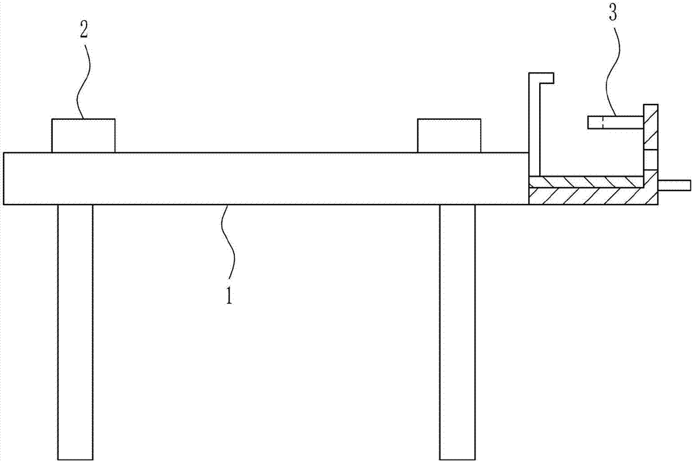
[0033] An ironing table for an electric iron, such as Figure 1-6 As shown, it includes a workbench 1, a fixing mechanism 2 and a placement mechanism 3. The fixation mechanism 2 is arranged symmetrically on the workbench 1, and the placement mechanism 3 is connected to the right side of the workbench 1.
Embodiment 2
[0035] An ironing table for an electric iron, such as Figure 1-6 As shown, it includes a workbench 1, a fixing mechanism 2 and a placement mechanism 3. The fixation mechanism 2 is arranged symmetrically on the workbench 1, and the placement mechanism 3 is connected to the right side of the workbench 1.
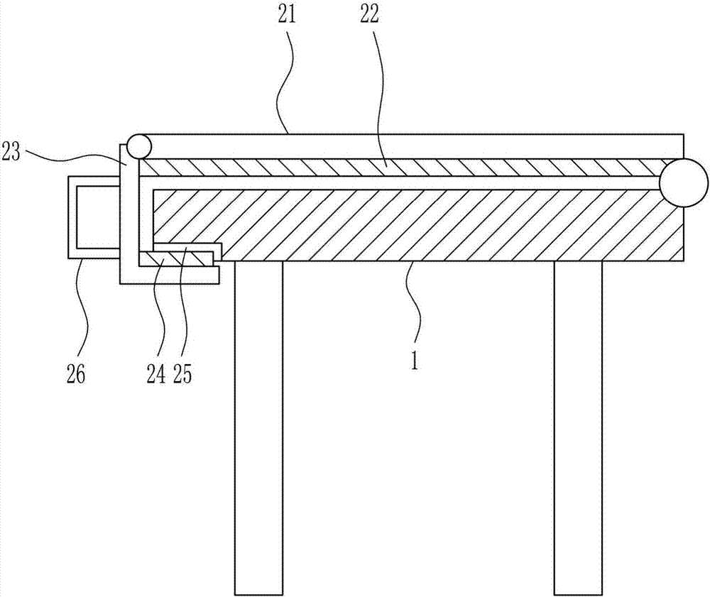
[0036] The fixing mechanism 2 includes a first rotating rod 21, a first rubber pad 22, a second rotating rod 23, a rubber block 24 and a handle 26. The bottom of 21 is connected with the first rubber pad 22, the rear end of the first rotating rod 21 is connected with the second rotating rod 23 in a rotating manner, and the upper part of the second rotating rod 23 is connected with a rubber block 24. Both are provided with a groove 25, the rubber block 24 cooperates with the groove 25, and the rear side of the second rotating rod 23 is connected with a handle 26.
Embodiment 3
[0038] An ironing table for an electric iron, such as Figure 1-6 As shown, it includes a workbench 1, a fixing mechanism 2 and a placement mechanism 3. The fixation mechanism 2 is arranged symmetrically on the workbench 1, and the placement mechanism 3 is connected to the right side of the workbench 1.
[0039]The fixing mechanism 2 includes a first rotating rod 21, a first rubber pad 22, a second rotating rod 23, a rubber block 24 and a handle 26. The bottom of 21 is connected with the first rubber pad 22, the rear end of the first rotating rod 21 is connected with the second rotating rod 23 in a rotating manner, and the upper part of the second rotating rod 23 is connected with a rubber block 24. Both are provided with a groove 25, the rubber block 24 cooperates with the groove 25, and the rear side of the second rotating rod 23 is connected with a handle 26.
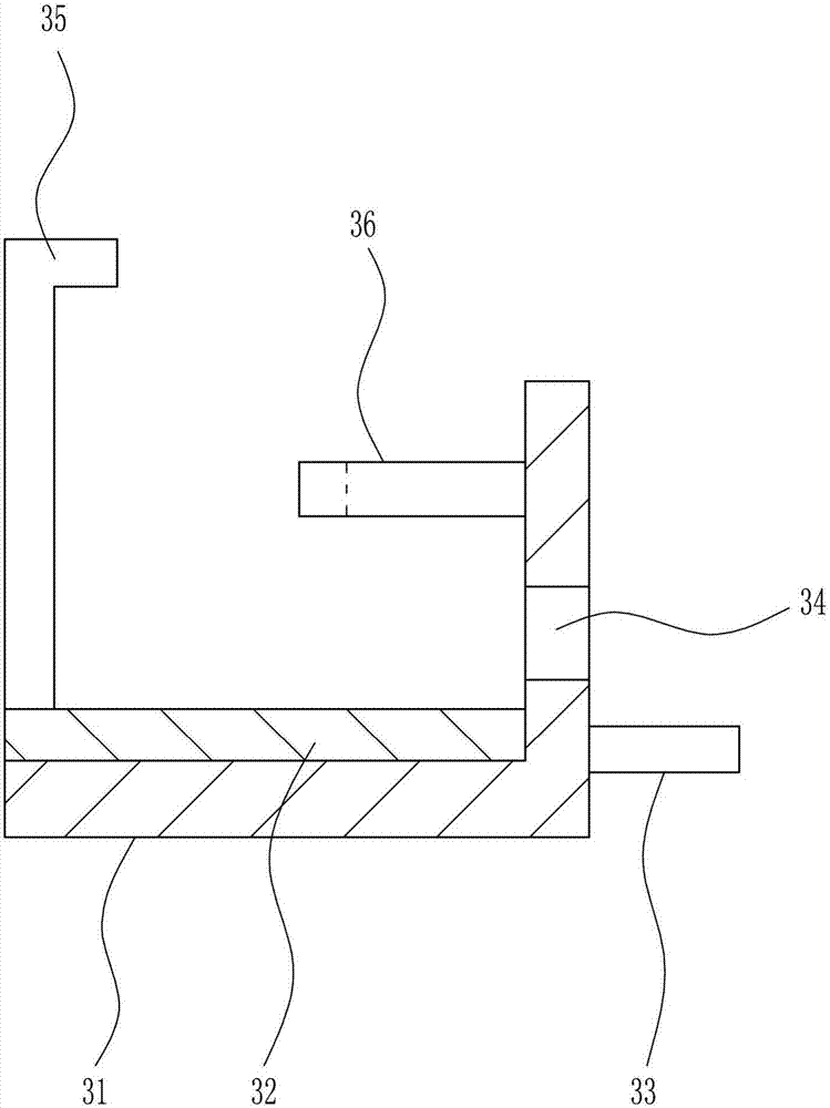
[0040] The placement mechanism 3 includes a placement frame 31, a second rubber pad 32, a first pole 33, a heat s...
PUM
 Abstract
Description
Claims
Application Information
 - R&D
- Intellectual Property
- Life Sciences
- Materials
- Tech Scout
- Unparalleled Data Quality
- Higher Quality Content
- 60% Fewer Hallucinations
Browse by: Latest US Patents, China's latest patents, Technical Efficacy Thesaurus, Application Domain, Technology Topic, Popular Technical Reports.
© 2025 PatSnap. All rights reserved.Legal|Privacy policy|Modern Slavery Act Transparency Statement|Sitemap|About US| Contact US: help@patsnap.com


