A girder erection method and a bridge erection machine for the working condition of a large longitudinal gradient

A bridge erecting machine and working condition technology, which is applied in the direction of erecting/assembling bridges, bridges, bridge construction, etc., and can solve problems such as how to construct bridge erecting machines

Active Publication Date: 2017-11-03
CHINA CONSTR FIFTH ENG DIV CORP LTD
View PDF5 Cites 10 Cited by
  • Summary
  • Abstract
  • Description
  • Claims
  • Application Information

AI Technical Summary

Problems solved by technology

[0004] The purpose of the present invention is to provide a beam erecting method and a bridge erecting machine used in the working condition of a large longitudinal slope, so as to solve the technical problem of how to construct the bridge erecting machine under the working condition of the maximum longitudinal slope exceeding 6%.

Method used


Image

  • A girder erection method and a bridge erection machine for the working condition of a large longitudinal gradient
  • A girder erection method and a bridge erection machine for the working condition of a large longitudinal gradient
  • A girder erection method and a bridge erection machine for the working condition of a large longitudinal gradient

Examples


Embodiment Construction

[0042] The embodiments of the present invention will be described in detail below with reference to the accompanying drawings, but the present invention can be implemented in various ways defined and covered by the claims.

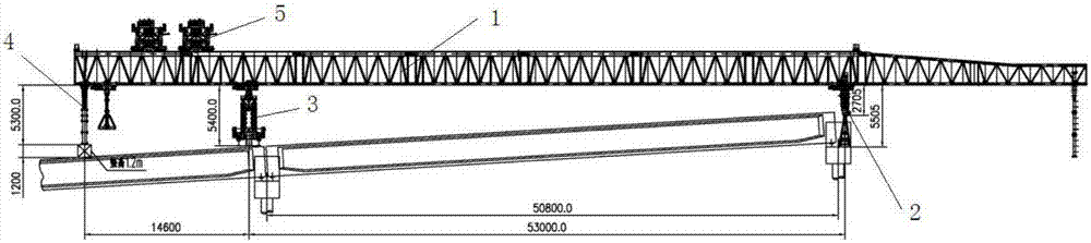
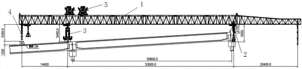
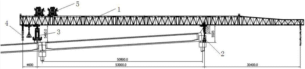
[0043] In view of the force bearing form of the front outriggers of the current bridge erecting machine, the lower part of the front outriggers of this application utilizes sliding friction to form a rigid connection with the beam; It is connected with the square column by a slipknot to form a flexible structure, and the height can be changed up and down.

[0044] And utilizing the front outrigger whose height can be changed up and down, the present application proposes the following beam erecting method under the working condition of large longitudinal slope.

[0045] This application is used in the girder erection method under the working condition of large longitudinal slope, including the following 15 steps, respectively with Figure 1 to Figure 15 co...


PUM


Abstract

The invention provides a girder erection method and a bridge erection machine for the working condition of a large longitudinal gradient. The bridge erection machine completes upslope erection under the working condition with the maximum longitudinal gradient exceeding 6% through continuous steps of lifting and lowering of a front supporting leg, jacking of a rear supporting leg, heightening of a rear auxiliary supporting leg, hanging of a hole passing carrier roller, adjusting and moving of a whole machine, slip of crown blocks, elevating of the whole machine, retreating of an oil cylinder of the rear auxiliary supporting leg, disengaging of the hole passing carrier roller; anchoring of the rear supporting leg and erecting of a T girder. The main part of the upper portion of the front supporting leg is a carrier roller box set which provides power for hole passing of a main girder and is connected with a square pillar via a slipknot to form a flexible structure. A stable structure is formed by one flexible structure and one rigid structure of the front supporting leg and the rear supporting leg, so that the upslope erection under the working condition with the maximum longitudinal gradient exceeding 6% can be finished.

Description

technical field [0001] The invention relates to the technical field of bridge erection, in particular to a beam erection method and a bridge erection machine used in large longitudinal slope working conditions. Background technique [0002] The bridge erecting machine generally adopts double guide beams and adopts a "steel-steel" structure (the rear outrigger and the guide beam form a rigid structure, the height can be adjusted, and the front outrigger and the guide beam are consolidated), the outrigger column is cylindrical, and the outrigger The adjustment height is small, and the longitudinal slope is generally not more than 3%, and the flat slope or the maximum 1% slope is erected, and the maximum longitudinal slope is not more than 5%. In the very rare working conditions where the longitudinal slope exceeds 3% in actual construction, it can be treated as a separate pad. [0003] However, under the condition that the maximum longitudinal slope exceeds 6%, the existing b...

Claims


Application Information

Patent Timeline
Patent Type & Authority Applications(China)
IPC IPC(8): E01D21/00
CPCE01D21/00
Inventor 唐恩宽易干明刘野蒋婧
Owner CHINA CONSTR FIFTH ENG DIV CORP LTD
Why Eureka
Try Eureka