Present-day fuel injectors suffer from an inability to operate at high frequencies.
This limits their applicability to advanced and emerging engine designs.
Additionally, present-day piezoelectric injectors do not directly actuate the member that controls the fuel flow.
These features cause this technology to be of great interest in tactical
missile systems, where the engine is destroyed during use.
Despite the many promises, researchers and designers of pulse detonation systems have struggled with an inability to control the timing and modulation of
fuel injection into the
combustion chamber of the pulse detonation engine.
Today, this injection control is essentially impossible to achieve using present-day fuel
injector technology and associated valve arrangements.
Another challenge associated with operating a pulse detonation
system is delivering differing fuel-to-air ratios at various locations in the detonation tube during each detonation cycle to maximize
engine efficiency.
First, present-day piezoelectric stack actuators used in fuel injectors do not provide direct actuation of the primary injector flow control member.
This multi-step process of indirect hydraulic actuation and amplification creates an inherent limit to the upper operational frequency of present-day injectors due to intrinsic response
lag.
Consequently, these
dual stage injectors generally will not support higher frequency operation necessary for the operation of a pulse detonation engine.
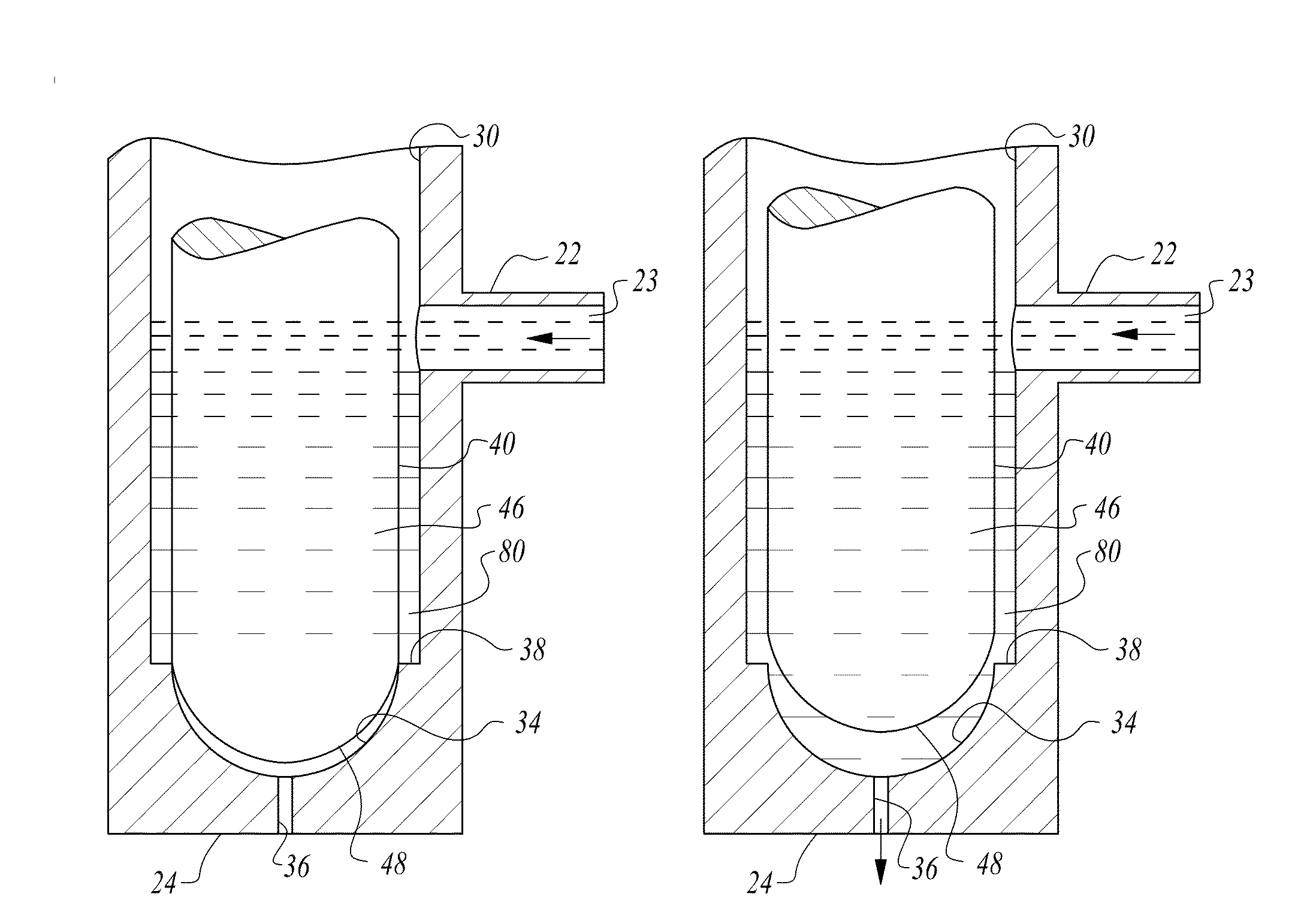
The shape of the pin results in over-balanced pressure, causing the pin to be seated on the orifice in a closed position.
This results in a directional net linear force and causes the pin to
lift off its seat and the
nozzle to open.
When a piezoelectric stack is used in the above manner, the overall
system is mechanically and operationally more complex.
Amplification of the displacement of the stack is required due to the extremely limited displacement of a piezoelectric stack relative to the displacement required to lift the pin a distance off its seat to enable the flow of fuel through an orifice.
This amplification typically requires more intricate flow arrangements within the body of the injector, including additional valves and additional sealing elements.
This response
lag impedes the ability of a hydraulically amplified injector, even those using
piezoelectric actuators, from operating at higher frequencies, such as those that might be required for pulse detonation engines or racing engines.
Present injector actuation methods have other limitations.
Unfortunately, this approach creates an even higher operational demand on the injector apparatus due to the multiplication of actuation cycles during each injection cycle.
A piloted valve requires less power to control and operate, but are noticeably slower.
Consequently, heretofore, this displacement limitation has forced piezoelectric actuation mechanisms in fuel injectors to be used in an amplification configuration rather than directly actuate the primary flow control member.
Necessarily, by definition, prior piezoelectric injector configurations that rely on displacement amplification do not deliver direct actuation of the flow control member.
Unfortunately, the inclusion of this mechanical feature introduces the limitation of a mechanical spring variable that limits
high frequency operation of the
actuator and reduces operational
longevity.
Each of these references fails to provide a solution for use of a piezoelectric
actuator having minuscule displacement wherein the piezoelectric
actuator directly drives the flow control member of the injector.
Additionally, and in further detail, these references suffer from one or more of the following disadvantages, which impede
high frequency operation and limit optimization throughout each combustion cycle to create
maximum efficiency.
These include: (1) indirect actuation; (2) partial spring actuation; (3) complex mechanisms with a plurality of components and parts; (4) operation only in a fully-open or fully-closed position; (5) desired displacement distances which would require prohibitively long piezoelectric stacks; (6) one or more boosters to achieve opening forces; (7) actuating mechanisms unable to accommodate sufficient displacement; (8) inclusion of spring elements likely to induce
valve float at higher frequency operation; (9) indirect actuation via hydraulic amplification resulting in lag and
hysteresis; (10) no
analog control of valve position; (11) inability to provide refined prestress on the piezoelectric stack to avoid placing it in tension; and (12) inability to adapt in real time to changing operating parameters or engine performance requirements.
Consequently, these other references do not provide for direct actuation.
Furthermore, Nakamura et al. does not describe a method for prestressing the piezoelectric stack.
General operation of the injector is either fully open or fully closed, with no ability to provide variable injection rates.
Additionally, it is unclear how the piezoelectric stack described by Nakamura et al. would provide sufficient displacement or contraction to move the needle sufficiently to unseat from the orifice, even with the inclusion of a supplementary spring.
In particular, for the
operational requirements associated with pulse detonation engines, the injector described by Nakamura et al. would neither enable sufficient flow nor operate at a sufficiently high frequency.
The system described by Boecking is a complex mechanism with insufficient displacement to move the pin sufficiently to support high volume
fuel delivery.
Additionally, Boecking's injector relies on the movement of a small
needle valve, which will inhibit the ability to deliver flow at higher rates.
Stoecklein's approach does not address issues of response lag nor
adaptation to operate at high frequencies.
Furthermore, although limited two-stage control is described, highly granular, essentially
analog control is not supported by Stoecklein's injector system.
It fails to provide
analog control of the valve position throughout its range of displacement.
Thus, it is unable to deliver highly granular control of the flow profile throughout each combustion / detonation / injection cycle.
Thus, the injector of Rauznitz et al. fails to provide direct actuation of the valve control member, limiting application in high frequency injection scenarios, and, fails to provide highly granular control of the fuel flow profile, limiting use, for example, in pulse detonation engines.
Finally, the injector is designed to accommodate small injector needles; it would not support large injector sizes to accommodate increased fuel flow.
Precise control and analog positioning of the
nozzle valve needle throughout its displacement is not possible.
Furthermore, the injector uses springs to bias the valve element into a closed position, which introduces complexity and will cause the injector to suffer float at higher frequency operation.
This mechanism adds complexity to the injector.
Furthermore, the Boecking injector is limited to operation in two discrete
modes: on and off.
The inclusion of the envelope and spring mechanisms in the injector of Takahashi introduces the problem of
valve float at higher operational frequencies, along with indirect actuation limitations.
In efforts to deliver adequate injection control in the operation of a pulse detonation engine, other challenges are presented by the operational theater in which pulse detonation engines are likely to be used.
For example, in certain military applications, there is little choice as to the available
fuel type and quality due to location in the battle field or region of deployment.
Where fuel is contaminated, there exists a high risk of injector orifice plugging.
The fuels can also be contaminated with particulate impurities or other diluting components, such as water.
The pulse detonation
combustor of Shimo et al. cannot readily adapt to differing thrust requirements, operational fuels, and operating environments.
Meholic's rotary valves still have drawbacks including the need for a sensor to pick up position and velocity of the valve.
Further, Meholic's valve is incapable of modulating the
duty cycle of the valve open-time.
This creates an inverse relationship of flow rate with frequency, which is undesirable for pulse detonation operations at higher speeds.
Although pressure can be increased to increase
mass flow rate, this creates other undesirable consequences such as warping of the valve plates.
Rotary valves also require rotary seals, which are subject to early failure.
The overall complexity of a rotary value solution for managing the flow of fuel or air into a pulse detonation engine is problematic for these and other reasons.
As with rotary valves, Daniau's approach would still suffer from the inverse relationship between valve
operating frequency and valve open period, creating an inability to modulate flow appropriately with frequency.
This mechanical configuration has limited upper operational frequency.
However, solenoid valves cannot operate at the desired high frequencies due to
hysteresis, significant phase lag, and overheating.
Additionally, solenoid valves do not have the ability to
handle high operating temperatures generated associated with the detonation process.
Consequently, there exists a substantial unmet need for an advanced fuel injector for use in pulse detonation engines wherein the fuel injector has
rapid response afforded by direct actuation of the flow control member while delivering dynamic, controlled and variable flow via analog displacement of the flow control member.

