Liquid supply mechanism and liquid cooling system

a technology of liquid cooling system and liquid supply mechanism, which is applied in the direction of liquid transferring device, positive displacement liquid engine, piston pump, etc., can solve the problems of liquid cooling system damage and insufficient cooling liquid, and achieve the effect of reducing the push force, high hydraulic pressure, and not affecting the heat dissipation efficiency of the liquid cooling system

Active Publication Date: 2016-12-15
COOLER MASTER CO LTD
View PDF3 Cites 18 Cited by
  • Summary
  • Abstract
  • Description
  • Claims
  • Application Information

AI Technical Summary

Benefits of technology

[0008]As mentioned in the above, the liquid supply mechanism of the invention is selectively connected to one of the liquid cooling head, the radiator, the pump, the liquid storage box and the tubes. When the cooling liquid reduces and then the hydraulic pressure of the liquid cooling system reduces, the resilient member of the liquid supply mechanism will push the plunger to move, so as to inject the cooling liquid from the chamber into the liquid cooling system. In other words, the liquid supply mechanism of the invention can supply the cooling liquid to the liquid cooling system automatically when the cooling liquid is insufficient, so as to prevent the liquid cooling system from being damaged due to insufficient cooling liquid. Furthermore, the damping member is disposed on the axial rod of the plunger and abuts against the inner wall of the axial hole. When the plunger is moving, a damping effect is generated between the damping member and the inner wall of the axial hole, so as to reduce the push force generated by the resilient member for the plunger. Accordingly, the invention can prevent the liquid cooling system from generating high hydraulic pressure while supplying the cooling liquid to the liquid cooling system, such that the heat dissipating efficiency of the liquid cooling system will not be affected.

Problems solved by technology

After the liquid cooling system is used for a long time, the cooling liquid will reduce due to vaporization, such that the cooling liquid may be insufficient.
If the user does not supply the cooling liquid in time, the liquid cooling system may be damaged due to insufficient cooling liquid.

Method used


Image

  • Liquid supply mechanism and liquid cooling system
  • Liquid supply mechanism and liquid cooling system
  • Liquid supply mechanism and liquid cooling system

Examples


Embodiment Construction

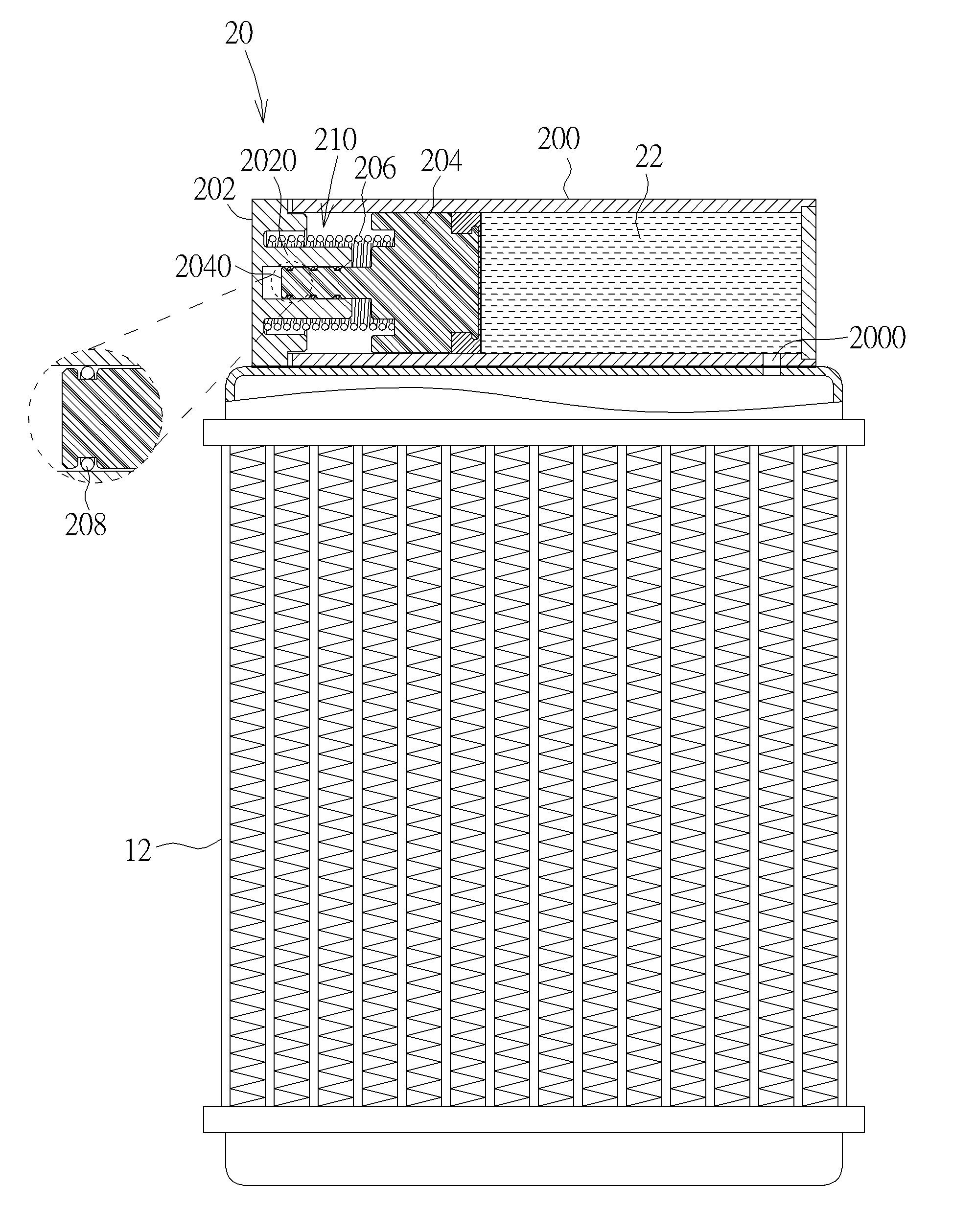
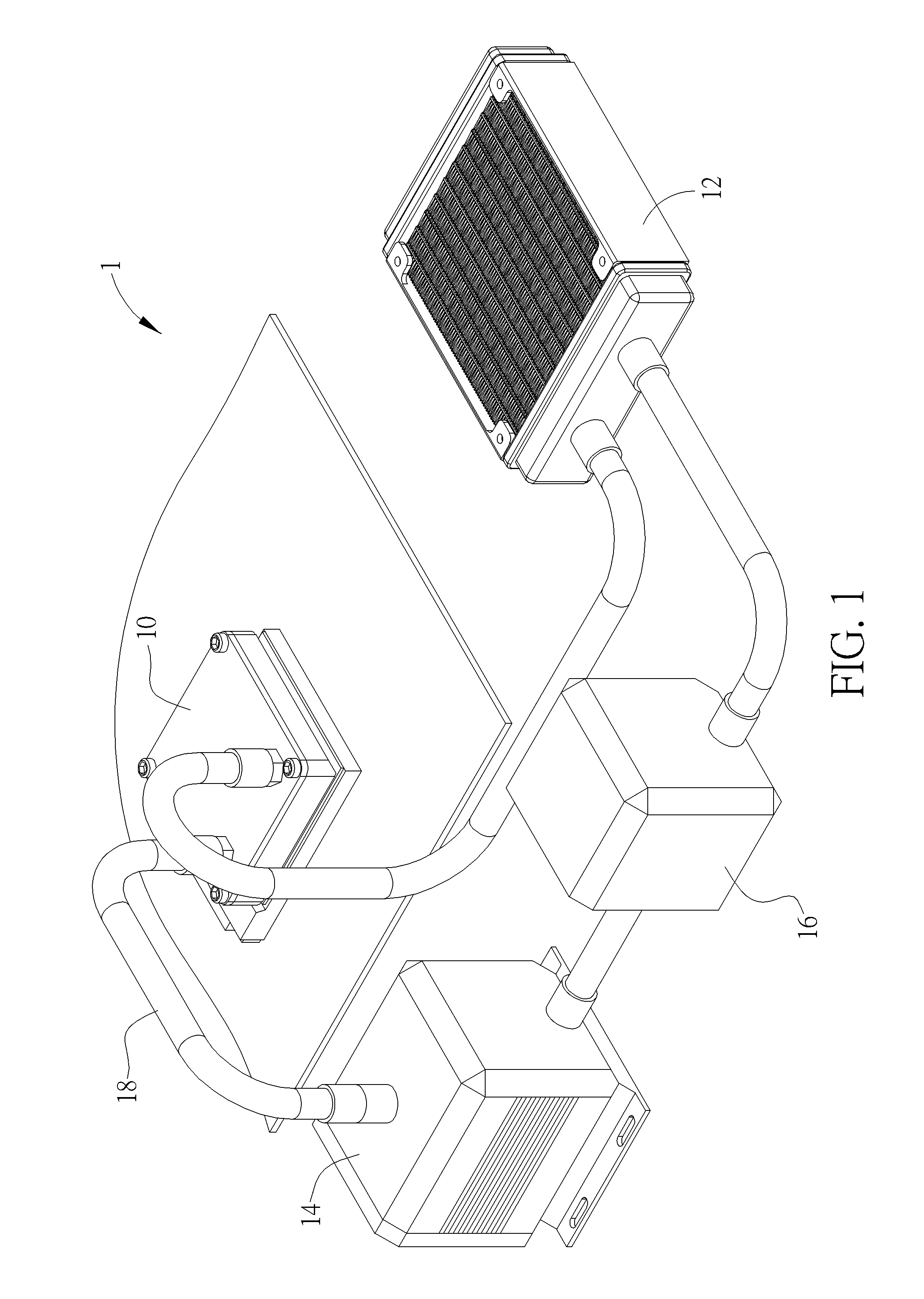
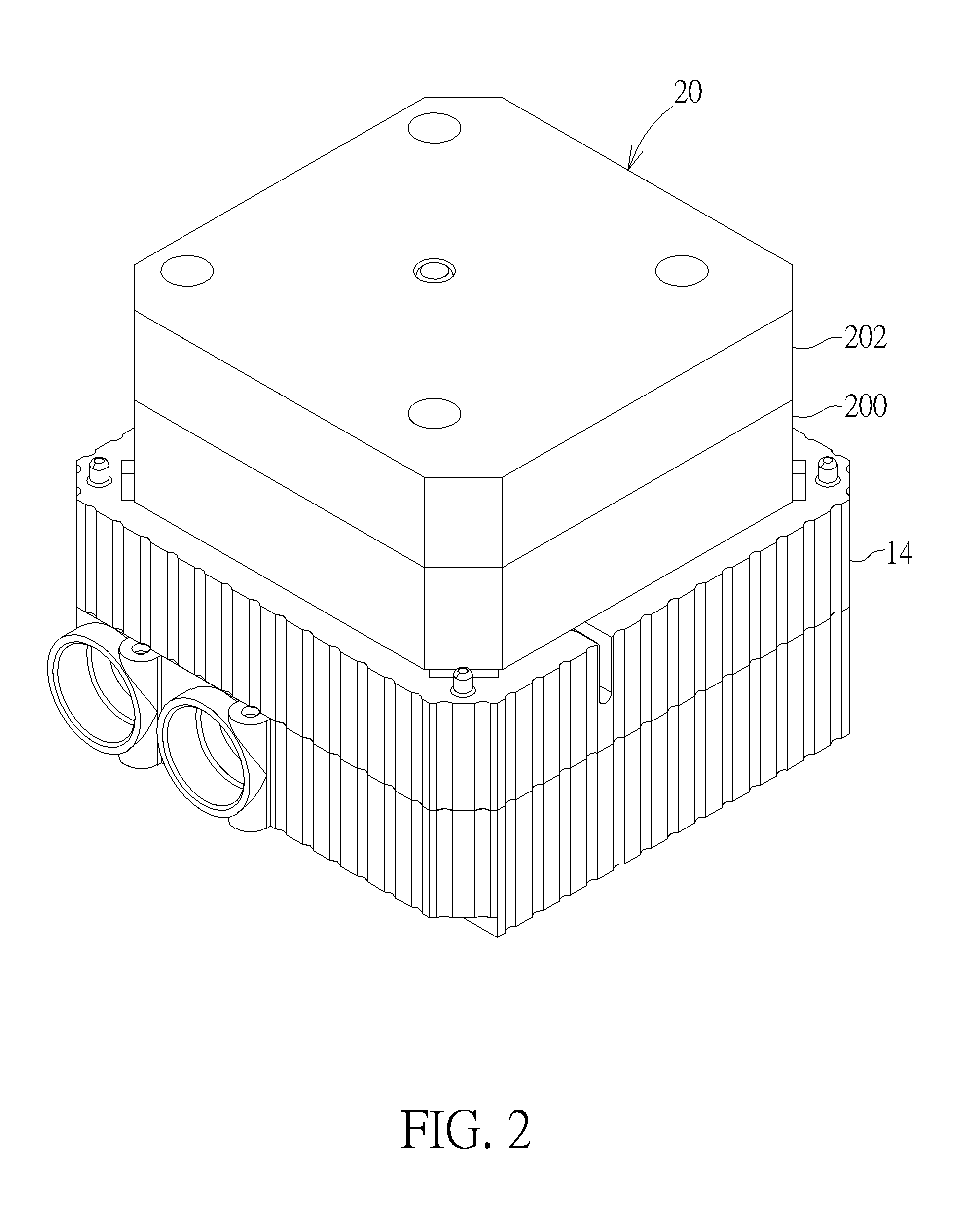
[0017]Referring to FIGS. 1 to 5, FIG. 1 is a schematic view illustrating a liquid cooling system 1 according to an embodiment of the invention, FIG. 2 is a schematic view illustrating a liquid supply mechanism 20 connected to a pump 14, FIG. 3 is an exploded view illustrating the liquid supply mechanism 20, FIG. 4 is a cross-sectional view illustrating the liquid supply mechanism 20 and the pump 14, and FIG. 5 is a cross-sectional view illustrating the plunger 204 shown in FIG. 4 after being pushed by the resilient member 206.

[0018]As shown in FIG. 1, the liquid cooling system 1 comprises a liquid cooling head 10, a radiator 12, a pump 14, a liquid storage box 16 and a plurality of tubes 18. The tubes 18 are connected between the liquid cooling head 10, the radiator 12, the pump 14 and the liquid storage box 16 and used for transporting a cooling liquid between the liquid cooling head 10, the radiator 12, the pump 14 and the liquid storage box 16. The cooling liquid (not shown in FI...


PUM


Abstract

A liquid supply mechanism includes a lower cover, an upper cover, a plunger, at least one resilient member and at least one damping member. The lower cover has a liquid outlet and the upper cover is connected to the lower cover. A chamber is formed between the lower cover and the upper cover. The chamber communicates with the liquid outlet and contains a cooling liquid. The upper cover has an axial hole. The plunger is movably disposed in the chamber. The plunger has an axial rod and the axial rod is inserted into the axial hole. The resilient member is disposed in the chamber. Opposite ends of the resilient member abut against the upper cover and the plunger. The damping member is disposed on the axial rod and abuts against an inner wall of the axial hole.

Description

BACKGROUND OF THE INVENTION[0001]1. Field of the Invention[0002]The invention relates to a liquid supply mechanism and a liquid cooling system and, more particularly, to a liquid supply mechanism capable of preventing a liquid cooling system from generating high hydraulic pressure while supplying a cooling liquid to the liquid cooling system.[0003]2. Description of the Prior Art[0004]In general, a liquid cooling system essentially consists of a liquid cooling head, a radiator, a pump and a liquid storage box connected through a plurality of tubes. When the liquid cooling system is dissipating heat from an electronic component, the pump transports a cooling liquid to the liquid cooling head, the cooling liquid absorbs the heat generated by the electronic component, and then the radiator cools the cooling liquid. After the liquid cooling system is used for a long time, the cooling liquid will reduce due to vaporization, such that the cooling liquid may be insufficient. If the user doe...

Claims


Application Information

Patent Timeline
Patent Type & Authority Applications(United States)
IPC IPC(8): H05K7/20B67D7/36
CPCB67D7/36H05K7/20272F04B9/02F04B11/0008F04B11/0033F04B23/02H01L23/473
Inventor LIAO, PEN-HUNGHUANG, SHIH-WEI
Owner COOLER MASTER CO LTD
Why Eureka
Try Eureka