

Constant velocity universal joint
- Summary
- Abstract
- Description
- Claims
- Application Information
AI Technical Summary
Benefits of technology
Problems solved by technology
Method used
Image

Examples
first embodiment
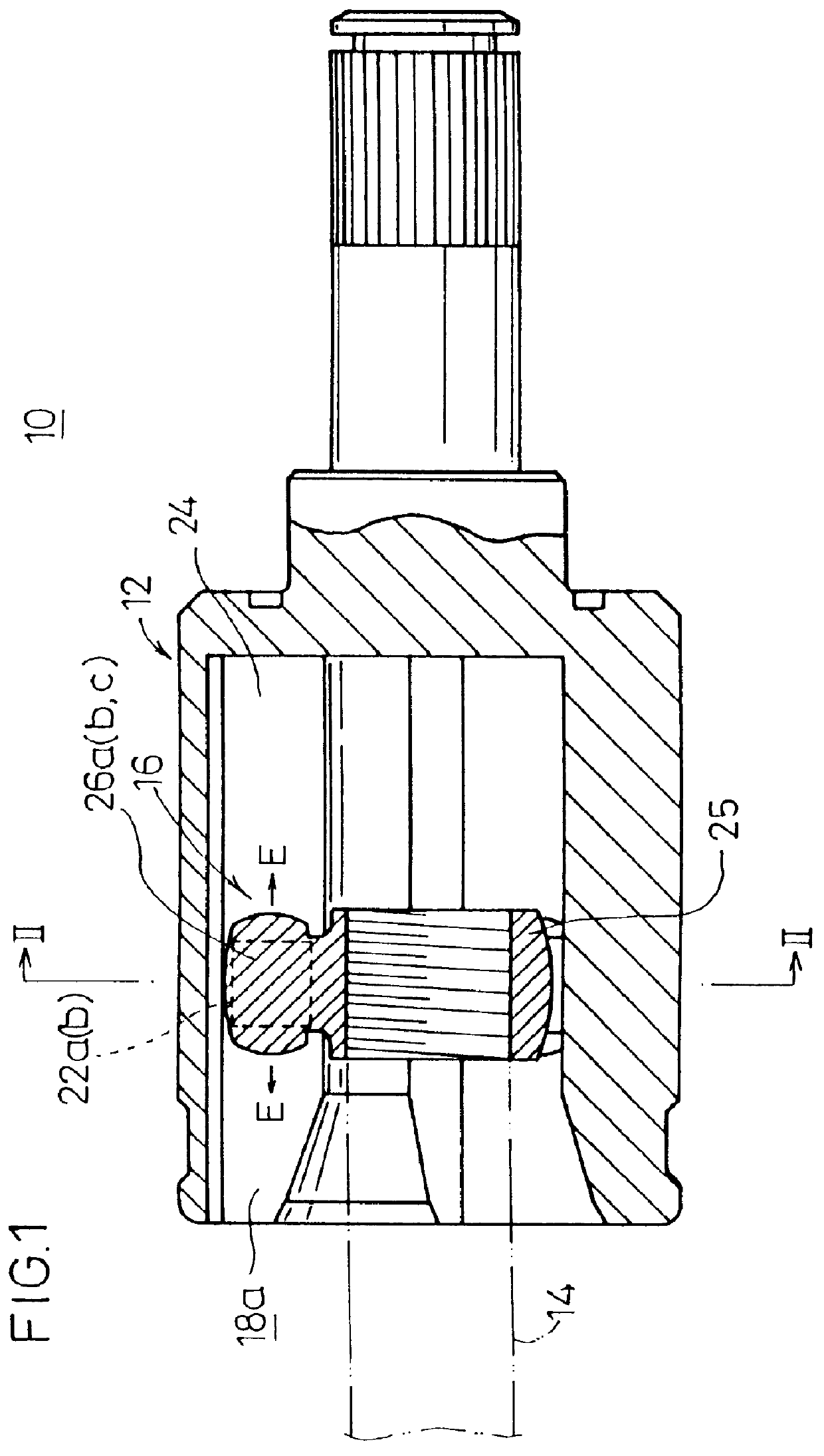
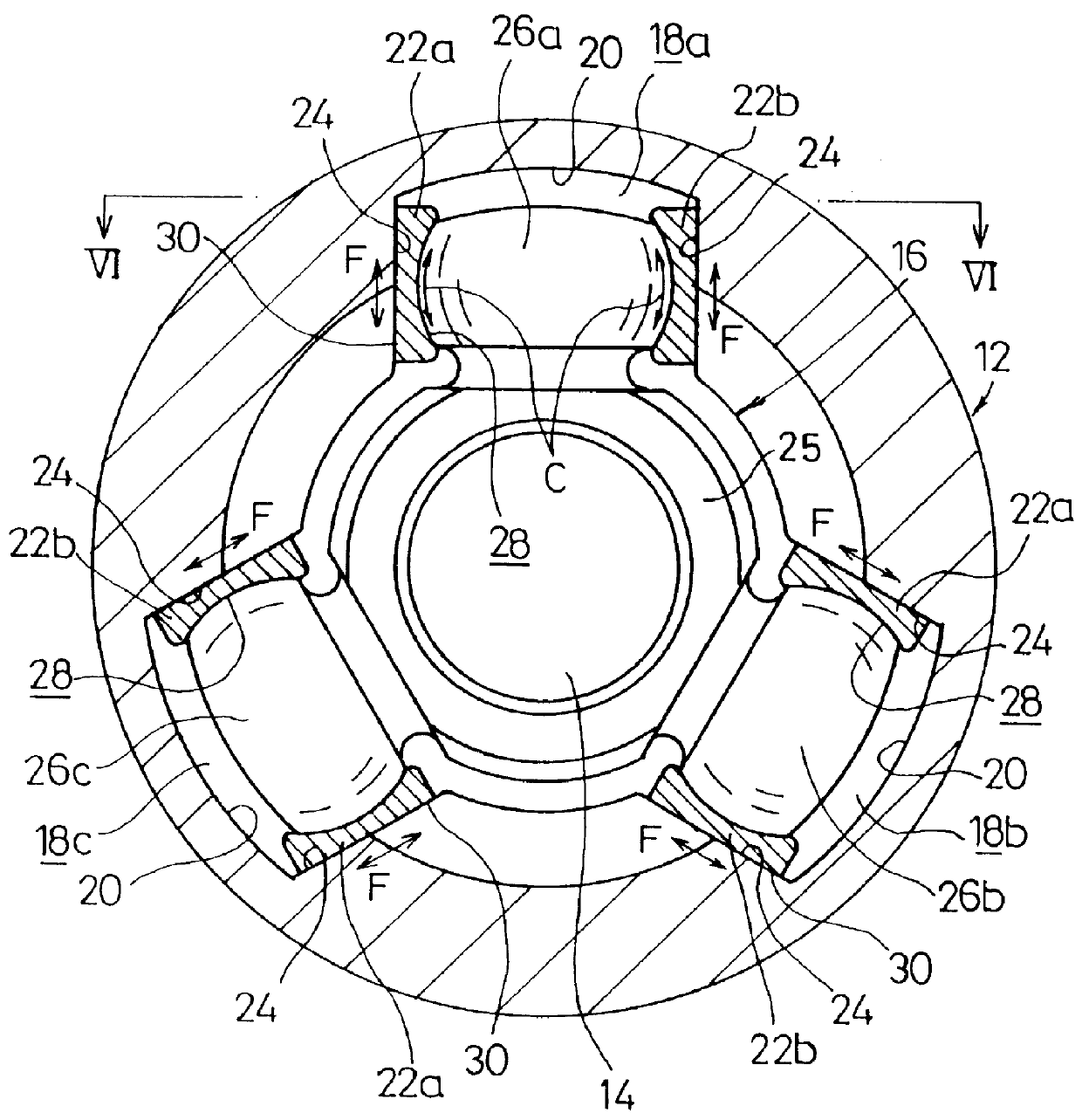
In FIGS. 1 and 2, reference numeral 10 indicates a constant velocity universal joint according to the present invention. The constant velocity universal joint 10 is basically comprises a cylindrical outer cup (outer member) 12 having an opening and integrally coupled to one end of an unillustrated first shaft, and an inner member 16 fixedly fixedly secured to one end of a second shaft 14 and accommodated in a hole of the outer cup 12.
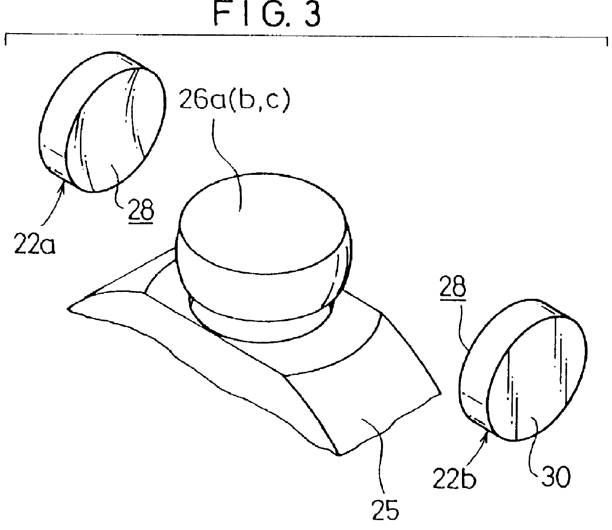
As shown in FIG. 2, three guide grooves 18a to 18c, which extend along the axial direction and which are spaced apart from each other by 120 degrees about the center of the axis, are formed on an inner circumferential surface of the outer cup 12. Each of the guide grooves 18a to 18c comprises a curved section 20 which is formed to have a curved cross section, and sliding surfaces (flat surface sections) 24 which are formed mutually opposingly on both sides of the curved section 20 for sliding slipper members 22a, 22b thereon as described later on. The s...
second embodiment
Next, a constant velocity universal joint 100 according to the present invention is shown in FIG. 11.
The constant velocity universal joint 100 comprises a cylindrical outer cup (outer member) 112 having an opening and integrally coupled to one end of an unillustrated first shaft, and an inner member 116 fixedly secured to one end of a second shaft 114 and accommodated in a hole of the outer cup 112. Three guide grooves 118a to 118c, which extend in the axial direction and which are spaced apart from each other by 120.degree. about the center of the axis respectively, are formed on an inner circumferential surface of the outer cup 112. As shown In FIG. 12, the guide groove 118a to 118c is composed of a ceiling section 120 which is curved along the outer circumference of the outer cup 112, and side curved sections 122a, 122b which are formed mutually opposingly on both sides of the ceiling section 120 and which are centered about a point C in each of the guide grooves 118a to 118c. Th...
fourth embodiment
Next, a constant velocity universal joint 180 according to the present invention is shown in FIG. 18.
Grooves 183a, 183b are formed on one outer wall section 140a of a holder 182 of the constant velocity universal joint 180, and grooves 183c, 183d are formed on the other outer wall section 140 thereof. Both end portions and central portions of the outer wall sections 140a, 140b are formed as stoppers 184a to 184f. Therefore, the grooves 183a and 183b, and the grooves 183c and 183d are separated from each other by the stoppers 184b, 184e respectively. One ball member 146a to 146d is provided rollably in each of the grooves 183a to 183d.
As clearly understood from FIG. 18, when the force in the circumferential direction of the outer cup 112 (in the direction indicated by an arrow P or Q in FIG. 18) is applied to the trunnion 126a to 126c, the force, which is exerted by the trunnion 126a to 126c on the abutting surface 136a, 136b of the holder 182, is always located between the ball memb...
PUM
 Abstract
Description
Claims
Application Information