

Low-noise lifting device
- Summary
- Abstract
- Description
- Claims
- Application Information
AI Technical Summary
Benefits of technology
Problems solved by technology
Method used
Image

Examples
first embodiment
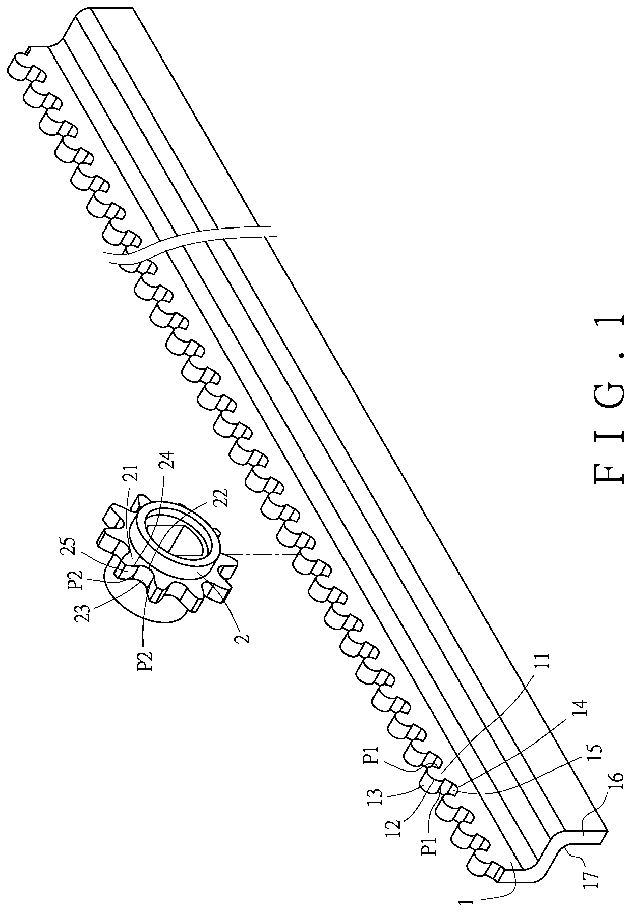
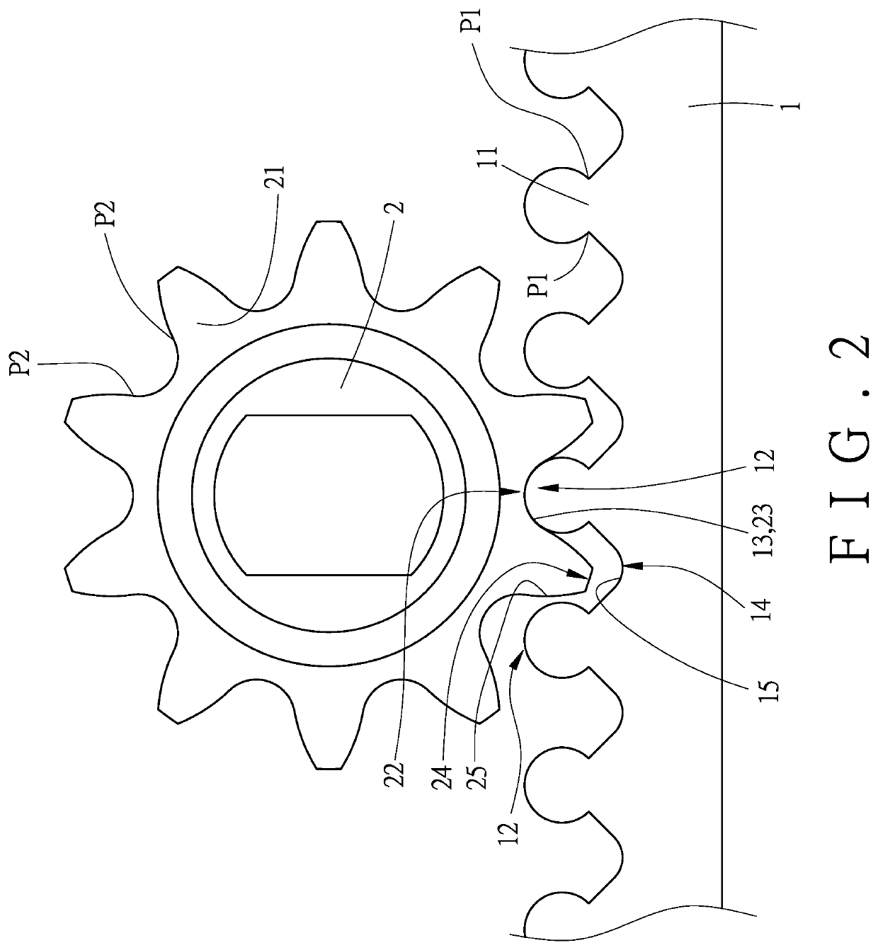
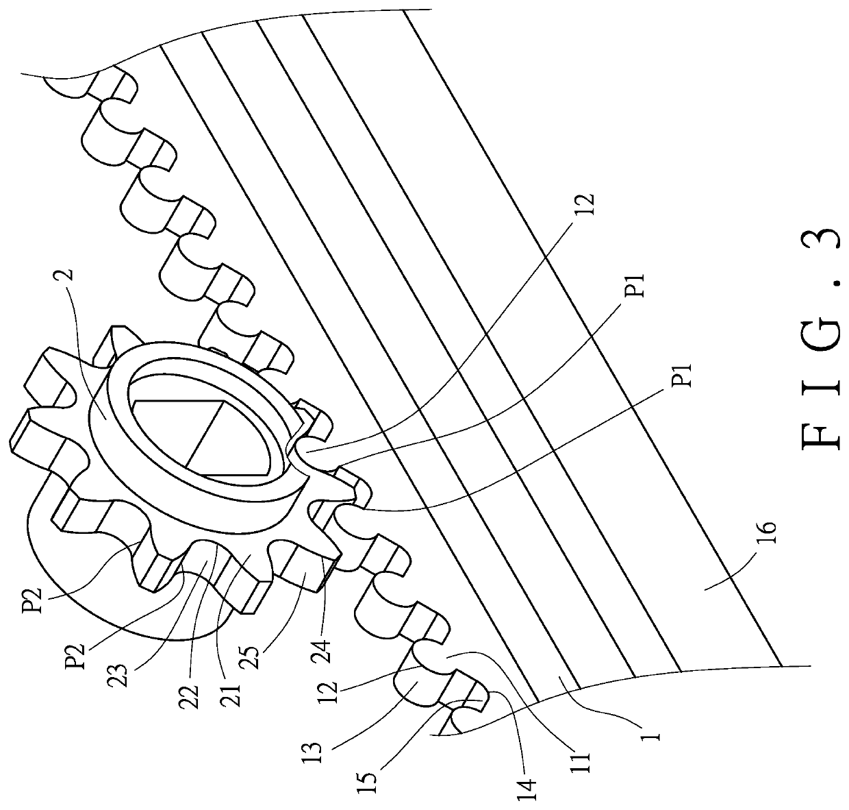
[0023]Referring to FIG. 1 and FIG. 2, the present invention comprises a rack (1) and a gear (2).
[0024]The rack (1) includes a plurality of first teeth (11) arranged in a straight line. Each of the first teeth (11) has a first crown portion (12). The first crown portion (12) is defined by a range between any two adjacent first nodes (P1). The surface of the first crown portion (12) is defined as a first contact surface (13) having a circular arc shape. A first root portion (14) is defined between the first crown portions (12) of every adjacent two of the first teeth (11). The surface of the first root portion (14) is defined as a first non-contact surface (15). In addition, the side of the rack (1) is provided with a retaining portion (16) that extends perpendicularly relative to the rack (1) and has an L-shaped cross section.
[0025]The gear (2) is in mesh with the rack (1) to drive the rack (1) to move linearly. The gear (2) includes a plurality of second teeth (21) arranged around t...
third embodiment
[0030]FIG. 8 and FIG. 9 illustrate a third embodiment of the present invention. the present invention is substantially similar to the first embodiment with the exceptions described hereinafter. The rack (4) is in the form of a U-shaped seat. The first crown portion (42) is a roller spanning the seat. The circumferential surface of the roller is defined as the first contact surface (43) for rotating. The rollers on the rack (4) can be relatively rolled, so that the circumferential surface of each roller is in close contact with the second contact surface (23) of the second root portion (22) of the gear (2), without any backlash at all. Therefore, during the transmission, the transmission contact can be relatively smooth to reduce the noise generated by the transmission contact, thereby achieving the same effect as the first embodiment.
[0031]When installed for lifting and lowering a table, as shown in FIG. 10, the two racks (4) are fixed to the opposite inner wall surfaces of an outer...
PUM
 Abstract
Description
Claims
Application Information