Hydraulic energy-saving system and reach stacker

An energy-saving system and hydraulic technology, applied in the directions of fluid pressure actuation system components, load suspension components, fluid pressure actuation devices, etc., can solve the problem of inability to retract, the potential energy of the telescopic boom is not reasonably utilized, and there is no boom retraction. energy-saving measures and other issues to achieve the effect of reducing system energy consumption

Active Publication Date: 2017-11-03
SANY MARINE HEAVY IND +1
View PDF16 Cites 2 Cited by
  • Summary
  • Abstract
  • Description
  • Claims
  • Application Information

AI Technical Summary

Problems solved by technology

[0002] The reachstackers in the prior art actively retract the telescopic boom through the hydraulic system, which cannot be retracted without actively supplying oil to the hydraulic system, and there is no energy-saving measure for boom retraction; the potential energy of the telescopic boom is not obtained when it is at a high elevation angle. Reasonable use, wasted in vain

Method used


Image

  • Hydraulic energy-saving system and reach stacker
  • Hydraulic energy-saving system and reach stacker
  • Hydraulic energy-saving system and reach stacker

Examples


Embodiment Construction

[0027] The present invention will be further described below in conjunction with the accompanying drawings and embodiments. It should be noted that, in the case of no conflict, the embodiments of the present application and the features in the embodiments can be combined with each other.

[0028] In the following description, many specific details are set forth in order to fully understand the present invention. However, the present invention can also be implemented in other ways than described here. Therefore, the protection scope of the present invention is not limited by the specific implementation disclosed below. Example limitations.

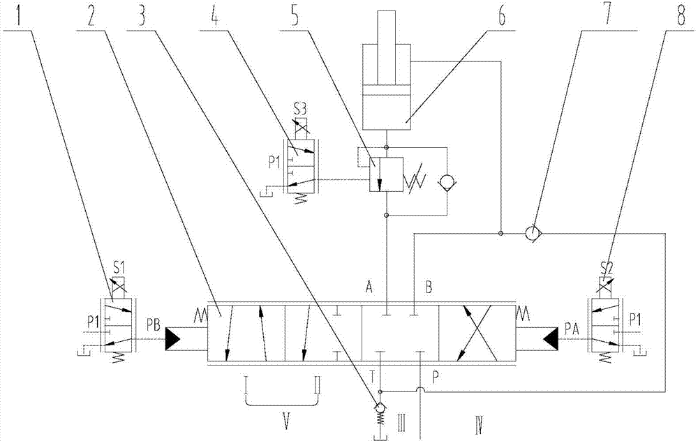
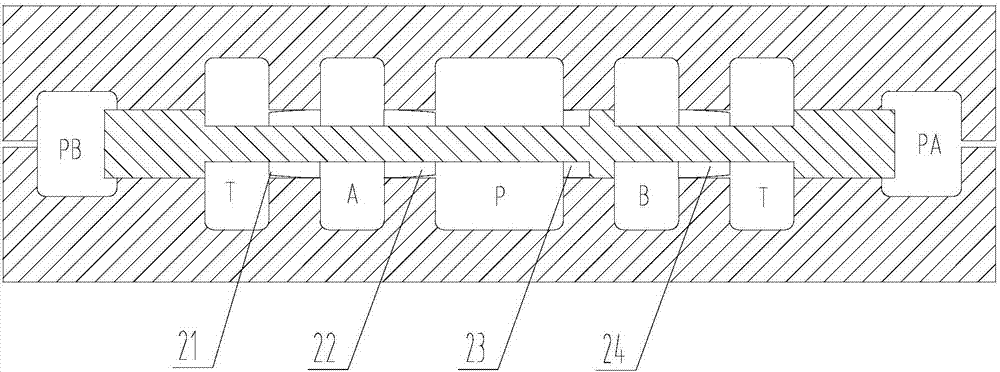
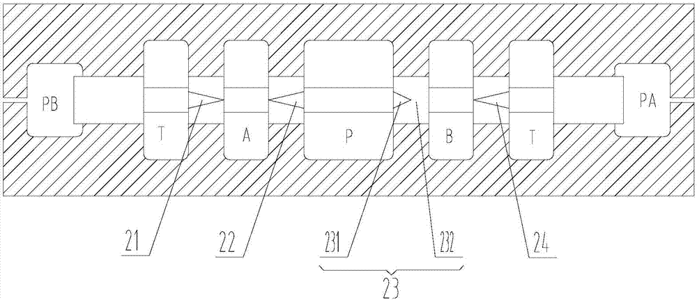
[0029] Such as Figures 1 to 7 As shown, according to the embodiment of the present invention, a hydraulic energy-saving system is provided, including a telescopic cylinder 6, the telescopic cylinder 6 is a single piston rod cylinder; a main valve 2 connected to the telescopic cylinder 6, the main valve 2 Including the working oil port A,...


PUM


Abstract

The invention provides a hydraulic energy-saving system. The hydraulic energy-saving system comprises a stretching and contracting oil cylinder and a main valve and furthermore comprises an oil supplementary valve; the stretching and contracting oil cylinder is a single-piston-rod oil cylinder; the main valve is connected with the stretching and contracting oil cylinder, the main valve comprises a work oil opening A, a work oil opening B, an oil inlet P connected with a hydraulic oil source and an oil return opening T connected with an oil tank; the work oil opening A is connected with a rodless cavity oil opening of the stretching and contracting oil cylinder (6), the work oil opening B is connected with a rod cavity oil opening of the stretching and contracting oil cylinder, the oil supplementary valve is connected between the hydraulic oil tank and the rod cavity oil opening of the stretching and contracting oil cylinder, and one-way communication from the hydraulic oil tank to a rod cavity of the stretching and contracting oil cylinder is achieved; and the main valve comprises an A-opening oil feeding throttling slot, an A-opening oil return throttling slot, a B-opening oil feeding throttling slot and a B-opening oil return throttling slot, and the B-opening oil feeding throttling slot comprises a throttling segment and an interception segment. The invention furthermore provides a reach stacker. According to the hydraulic energy-saving system provided by the invention, retraction of an arm frame is achieved through the gravitational potential energy of a stretching and contracting arm, and system energy consumption is lowered.

Description

technical field [0001] The invention relates to the field of engineering machinery, more specifically, to a hydraulic energy-saving system and a front hanger. Background technique [0002] The reachstackers in the prior art actively retract the telescopic boom through the hydraulic system, which cannot be retracted without actively supplying oil to the hydraulic system, and there is no energy-saving measure for boom retraction; the potential energy of the telescopic boom is not obtained when it is at a high elevation angle. Reasonable use, wasted in vain. [0003] Therefore, it is the problem to be solved by the present invention to provide a hydraulic energy-saving system that uses the gravitational potential energy when the telescopic boom is in a state of high elevation to realize retraction of the boom and reduce system energy consumption. Contents of the invention [0004] The technical problem to be solved by the present invention is to provide a hydraulic energy-sa...

Claims


Application Information

Patent Timeline
Patent Type & Authority Applications(China)
IPC IPC(8): F15B11/08F15B13/04F15B21/02B66C13/16B66C13/20
CPCB66C13/16B66C13/20F15B11/08F15B13/0402F15B21/02F15B21/14F15B2013/0413F15B2211/88
Inventor 袁朋周东才杨浪
Owner SANY MARINE HEAVY IND
Why Eureka
Try Eureka