Two-way self-locking electric push rod

An electric push rod, two-way self-locking technology, applied in the direction of electric components, electrical components, electromechanical devices, etc., can solve the problems of high cost, difficult push rod, complex structure, etc.

Pending Publication Date: 2017-11-03
ZHEJIANG JIECHANG LINEAR MOTION TECH
View PDF31 Cites 5 Cited by
  • Summary
  • Abstract
  • Description
  • Claims
  • Application Information

AI Technical Summary

Problems solved by technology

[0002] Electric push rods, generally also called linear actuators, its main working principle is to drive the transmission screw to rotate through the motor, and the transmission nut is set on the transmission screw, and when the transmission screw rotates, it drives the nut to reciprocate. Self-locking device to prevent the electric push rod from slipping under external force after the motor stops running, causing the electric push rod to lose lock. The existing electric push rod self-locking structure is basically realized by torsion spring. The main principle is to use When the drive screw is reversed, the torsion spring will hold the drive screw tightly to achieve braking, but the self-locking device on the existing electric push rod can only realize self-locking in the direction of the push rod, or retract Direction self-locking, but the same push rod is difficult to achieve self-locking in two directions at the same time, even if there is, the structure is more complicated and the cost is relatively high

Method used


Image

  • Two-way self-locking electric push rod
  • Two-way self-locking electric push rod
  • Two-way self-locking electric push rod

Examples


Embodiment 1

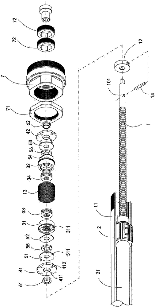
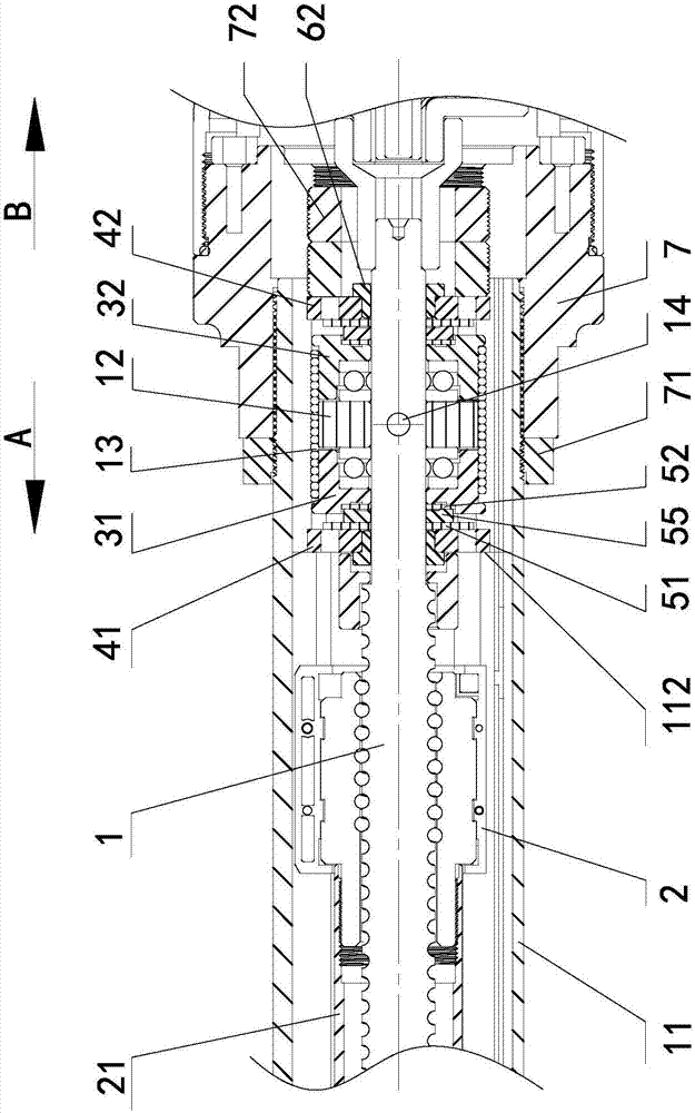
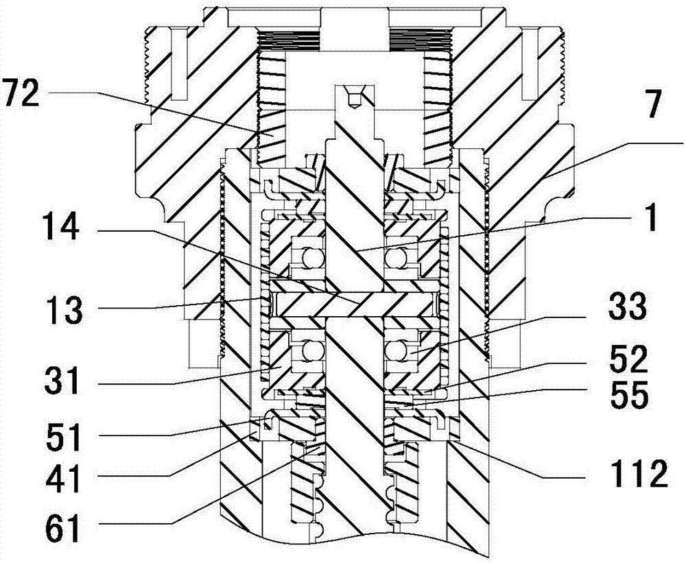
[0030] Such as Figure 1 to Figure 4 As shown, this embodiment shows a two-way self-locking electric push rod. This embodiment is mainly used in solar thermal power generation technology to drive heliostats. Of course, it can also be used for other pairs of two-way self-locking. In the field where the precision of the electric push rod is high, the main structure of the two-way self-locking electric push rod in this embodiment includes a motor, the motor is connected to a drive screw 1, and the drive screw 1 is connected to a drive nut 2 , the motor is installed in the base, the base is fixedly connected with the outer tube 11, and the drive nut 2 is fixedly connected with the inner tube 21, when the motor drives the drive screw 1 to rotate, the drive nut 2 is opposite to the drive screw 1 move. On the whole, relative movement between the inner tube 21 and the outer tube 11 is achieved, and the outermost end of the inner tube 21 is used to drive the heliostat to rotate.

[0...


PUM


Abstract

The invention discloses a two-way self-locking electric push rod, and belongs to the technical field of linear transmission. The two-way self-locking electric push rod comprises an outer pipe, an inner pipe, a transmission lead screw and a transmission nut; the transmission lead screw is rotationally mounted in the outer pipe; the transmission nut is fixedly connected with the inner pipe; the electric push rod is provided with a self-locking device; the self-locking device comprises a left bearing base, a right bearing base, and a brake disc arranged between the left bearing base and the right bearing base for tightly bonding with the left bearing base or the right bearing base; the left bearing base and the right bearing base are mounted on the outer pipe; the brake disc is fixedly mounted on the transmission lead screw; a self-locking torsion spring is arranged at the outer periphery of the brake disc in a sleeving mode; and the self-locking torsion spring is in interference fit with the outer periphery of the left bearing base, the outer periphery of the right bearing base and the outer periphery of the brake disc. The two-way self-locking electric push rod has the advantages of capability of realizing two-way self-locking, simple structure and stable self-locking.

Description

【Technical field】 [0001] The invention relates to a two-way self-locking electric push rod, which belongs to the technical field of linear transmission. 【Background technique】 [0002] Electric push rods, generally also called linear actuators, its main working principle is to drive the transmission screw to rotate through the motor, and the transmission nut is set on the transmission screw, which drives the nut to reciprocate when the transmission screw rotates. Usually, the electric push rod is equipped with Self-locking device to prevent the electric push rod from slipping under external force after the motor stops running, causing the electric push rod to lose lock. The existing electric push rod self-locking structure is basically realized by torsion spring. The main principle is to use When the drive screw is reversed, the torsion spring will hold the drive screw tightly to achieve braking, but the self-locking device on the existing electric push rod can only realize ...

Claims


Application Information

Patent Timeline
Patent Type & Authority Applications(China)
IPC IPC(8): F16H25/24H02K7/06
CPCH02K7/06F16H25/2454
Inventor 陆小健张甲程云山
Owner ZHEJIANG JIECHANG LINEAR MOTION TECH
Why Eureka
Try Eureka