Vertical-axis wind-power generation equipment and power generation method

A technology for wind power generation equipment and vertical axis, which is applied to wind power generation, wind turbines, and wind turbines at right angles to the wind direction, etc., can solve the problems of high manufacturing, transportation, installation, and maintenance costs, low vertical axis fan efficiency, and blade forming. Difficulty and other problems, to achieve the effect of reducing material costs, reducing site requirements, and flexible design

Pending Publication Date: 2019-05-17
静润能源(广东)有限公司
View PDF0 Cites 4 Cited by
  • Summary
  • Abstract
  • Description
  • Claims
  • Application Information

AI Technical Summary

Problems solved by technology

One of the reasons why the existing vertical-axis high-power fans are not as popular as the horizontal-axis fans is that the greater the power, the larger the blades, and the weight of the blades makes it difficult to enlarge the cantilever beam structure. Support, it is possible to make the blade larger, but the blade moves in a circle around the vertical axis. Although the blade is connected to the vertical axis, it can be adjusted at a certain angle, but within the range of 360° around the vertical axis, the blade in some areas It is to generate negative resistance, which is not as good as the horizontal axis blades that can generate lift during rotation
Therefore, the efficiency of existing vertical axis fans is relatively low
[0004] Due to the large rotating diameter of the impeller, the existing horizontal axis high-power fans need to install towers with high installation height and high strength requirements, and need to erect motor gearboxes and other components at high altitudes. Therefore, the costs of manufacturing, transportation, installation, and maintenance are very high. High, and the blade forming is difficult

Method used


Image

  • Vertical-axis wind-power generation equipment and power generation method
  • Vertical-axis wind-power generation equipment and power generation method
  • Vertical-axis wind-power generation equipment and power generation method

Examples


Embodiment 1

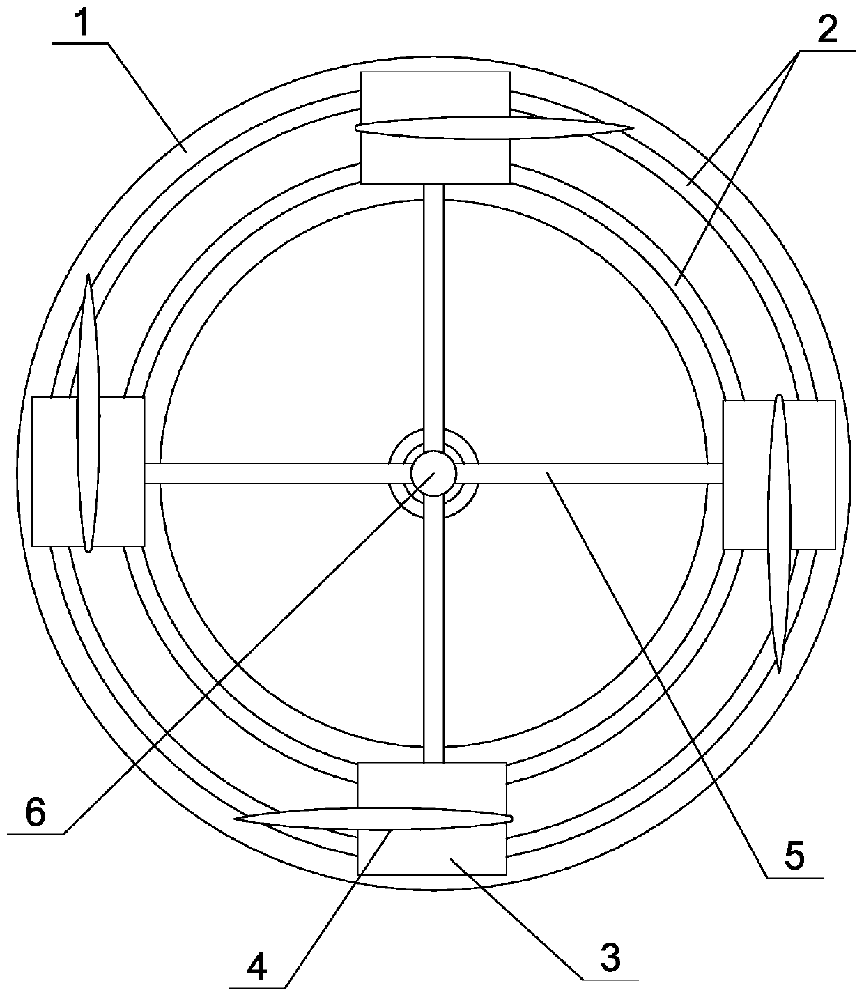
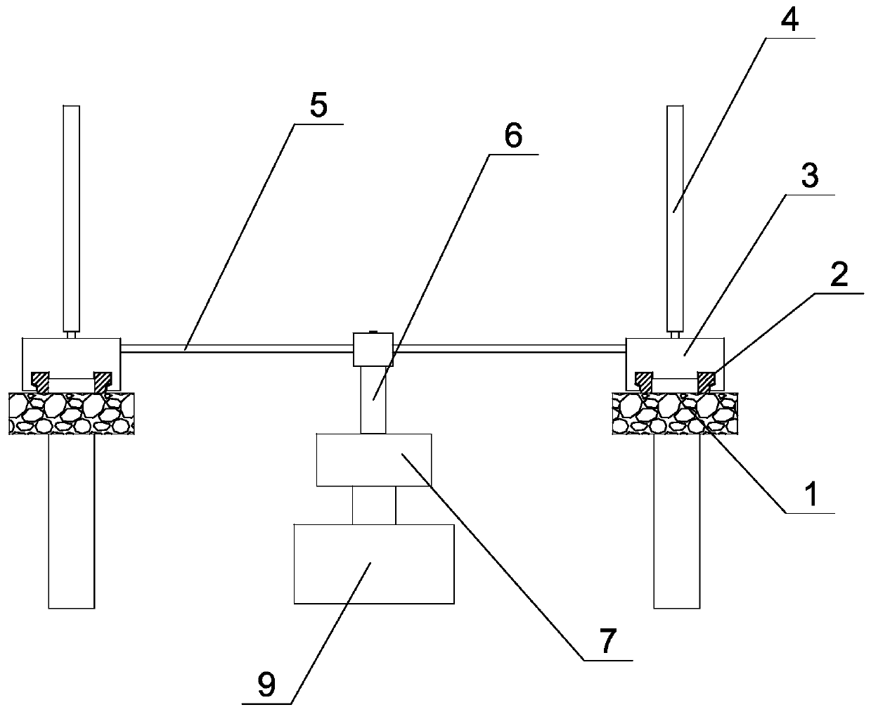
[0025] like Figure 1 ~ Figure 3As shown, the vertical axis wind power generation equipment of this embodiment includes a base 1, a ring track 2, four railcars 3, a generator 9, and a vertical main shaft 6 that drives the generator 9 to generate electric energy. The generator 9 is set On the ground or near the ground, the annular track 2 is fixed on the base 1. In this embodiment, the base 1 is a civil construction base with low cost. Of course, a steel structure base can also be used, so Said ring track 2 is double track, better stability, also can adopt the form of monorail of course, described rail car 3 is erected on the described ring track 2, and described rail car 3 can move circularly along described ring track 2, A lifting blade 4 is installed on each said rail car 3, and each said rail car 3 is fixedly connected with said vertical main shaft 6 by a crossbeam 5, and each said rail car 3 takes said vertical main shaft 6 as geometric center Uniform and balanced layout,...

Embodiment 2

[0029] Such as Figure 4 As shown, the difference between the vertical axis wind power generation equipment of this embodiment and Embodiment 1 is that in this embodiment, there are two opposite and symmetrically arranged rail cars 3, and three lift blades 4 are installed on each of the rail cars 3 Each rail car 3 is fixedly connected to the vertical main shaft 6 through two beams 5, which can enhance the structural strength and reduce the size of each beam 5.

[0030] The remaining features of this embodiment are the same as those of Embodiment 1.

Embodiment 3

[0032] Such as Figure 5 As shown, the difference between the vertical axis wind power generation equipment of this embodiment and Embodiment 2 is that in this embodiment, there are three railcars 3 arranged symmetrically at an angle of 120° along the circumference, and three railcars 3 are installed on each of the railcars 3. Each of the rail cars 3 is fixedly connected to the vertical main shaft 6 through a crossbeam 5, and the blade driving device is driven by a small motor device.

[0033] All the other features of this embodiment are the same as those of Embodiment 2

[0034] The vertical axis wind power generation equipment of the present invention is a vertical axis wind power generation equipment with a brand new structure. By using the rail car 3 as the load-bearing carrier and transmission carrier of the lifting blade 4, the conventional vertical axis wind power generation equipment avoids the The cantilever beam structure in which the blades are directly connected ...


PUM


Abstract

The invention discloses vertical-axis wind-power generation equipment and a power generation method. The vertical-axis wind-power generation equipment comprises a pedestal (1), a ring-shaped rail (2),at least two rail vehicles (3), a power generator (9) and a vertical principal axis (6), wherein the ring-shaped rail (2) is fixedly arranged on the pedestal (1); the rail vehicles (3) are arranged on the ring-shaped rail (2); at least one lifting blade (4) is mounted on each rail vehicle (3); and each rail vehicle (3) is fixedly connected to the vertical principal axis (6) through at least one beam (5), the lifting blade (4) receives wind to generate lifting force to push the rail vehicle (3) to perform ring-shaped movement along the ring-shaped rail (2), the vertical principal axis (6) is driven by a beam (5) to rotate to drive the power generator (9) to generate electric energy. The power generation method comprises the following steps: acquiring environment wind direction informationthrough a blade master control device, and obtaining real-time direction information of the rail vehicle (3); enabling the blade master control device to emit a control signal to the blade drive device, and regulating the angle of each lifting blade (4) according to the environment wind direction and the current position of the corresponding rail vehicle (3).

Description

technical field [0001] The invention relates to a vertical axis wind power generation equipment; in addition, the invention also relates to a power generation method. Background technique [0002] Clean energy is the mainstream development direction of the world today. Wind power is a kind of clean energy, and it is widely used in environments with abundant wind resources. Wind power generation equipment is divided into horizontal axis and vertical axis in terms of structure. At present, horizontal axis wind power generation has grown to 15MW, its tower height exceeds 200 meters, and its impeller diameter exceeds 180 meters. This is very important for the design, installation, maintenance and Reliability presents enormous challenges. On land, the power increase of land wind turbines is limited due to the difficulty of transportation due to the excessive length of the blades; for offshore wind turbines, in extreme weather conditions such as typhoons, it will cause irreversi...

Claims


Application Information

Patent Timeline
Patent Type & Authority Applications(China)
IPC IPC(8): F03D9/25F03D3/06F03D3/00F03D13/20F03D7/06
CPCY02E10/728Y02E10/74
Inventor 张攻坚
Owner 静润能源(广东)有限公司
Why Eureka
Try Eureka