
Stress measuring device based on deflection method

A stress measurement and fine-tuning device technology, applied in the measurement device, using stable tension/pressure to test material strength, strength characteristics, etc., can solve the problems of data dispersion, limited loading capacity, data distortion, etc., to achieve accurate measurement results, The effect of reducing the floor space and simplifying the accuracy

Active Publication Date: 2019-07-02
NORTHWESTERN POLYTECHNICAL UNIV
View PDF5 Cites 0 Cited by
  • Summary
  • Abstract
  • Description
  • Claims
  • Application Information

AI Technical Summary

Problems solved by technology

Generally, the smaller the measured data, the lower the reliability of the measured value, and the greater the influence of human manipulation factors. If weights are used for loading, due to the limited loading capacity of weights, it is impossible to make the equal-strength beam produce a greater stress state. Therefore, the experimental device has the disadvantage that it can only be tested under a low stress state, which will affect the accuracy of the measurement results; the quality of the strain gauge paste usually directly affects the accuracy and reliability of the measurement results. If it is not high, it will lead to data dispersion and data distortion, so that the measurement points will fail

Method used


Image

  • Stress measuring device based on deflection method
  • Stress measuring device based on deflection method
  • Stress measuring device based on deflection method

Examples


Embodiment Construction

[0021] The following will clearly and completely describe the technical solutions in the embodiments of the present invention with reference to the accompanying drawings in the embodiments of the present invention. Obviously, the described embodiments are only some, not all, embodiments of the present invention. Based on the embodiments of the present invention, all other embodiments obtained by persons of ordinary skill in the art without making creative efforts belong to the protection scope of the present invention.

[0022] In order to make the above objects, features and advantages of the present invention more comprehensible, the present invention will be further described in detail below in conjunction with the accompanying drawings and specific embodiments.

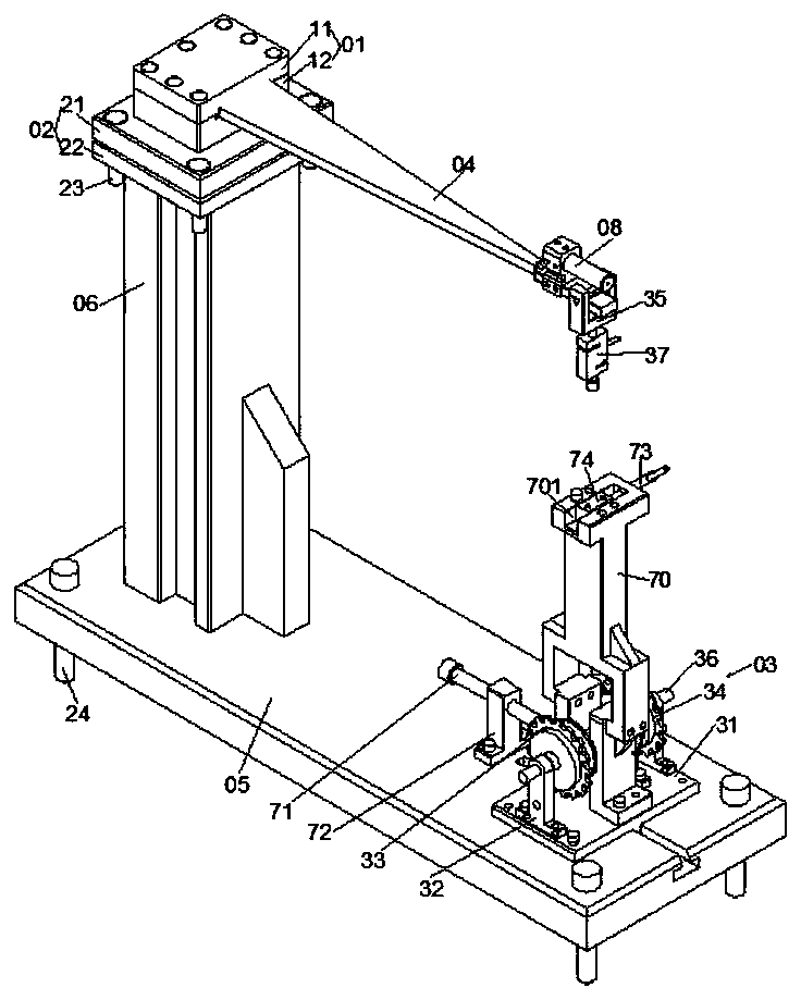
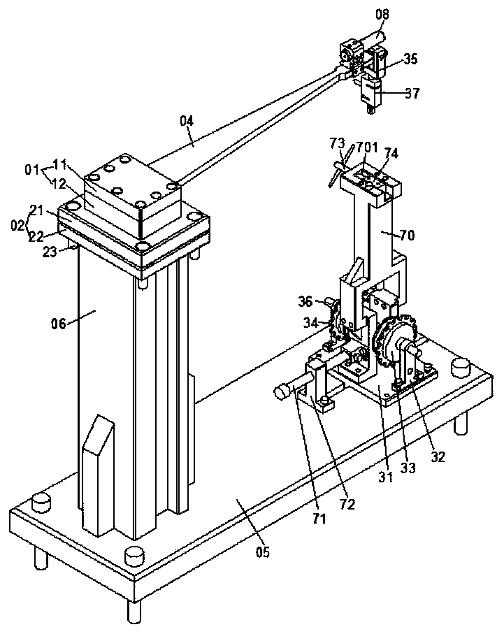
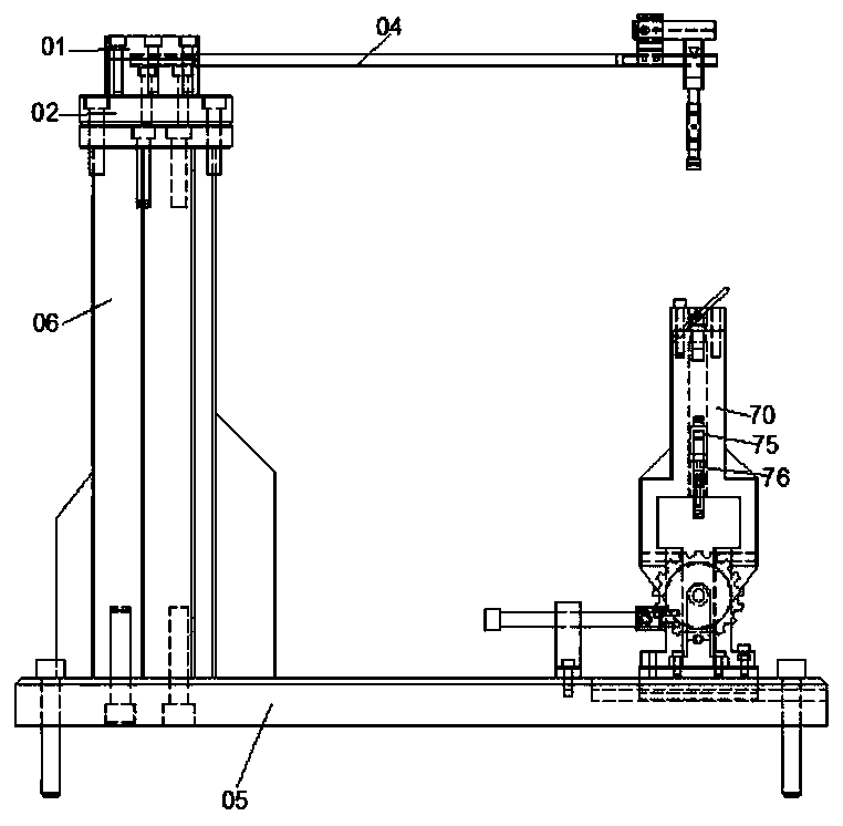
[0023] Such as figure 1 , 2 As shown, a stress measurement device based on the deflection method of the present invention includes a beam clamping device 01, a level adjustment device 02, a force loading device 0...


PUM


Abstract

The invention discloses a stress measurement device based on a deflection method. The stress measurement device based on the deflection method comprises a girder clamping device, a force application loading device, a homogeneous girder and a supporting plate main body, wherein the beam clamping device is fixed on the supporting plate main body; a clamping end of the homogeneous girder is placed on the girder supporting device; a quasi cross laser device is mounted at a force application end of the homogeneous girder; the force application loading device comprises a loading supporting plate, a groups of supports which are fixed on the loading supporting plate, a stress gear, a unidirectional ratchet, a rope and a loading cutting edge; the stress gear and the unidirectional ratchet are fixed on a loading shaft; the loading cutting edge is fixed at the force application end of the homogeneous girder; a pull-pressure sensor is mounted on the loading cutting edge; one end of the rope is fixed on the stress gear; and the other end of the rope is fixed on the pull-pressure sensor. By the stress measurement device based on the deflection method, the homogeneous girder can be in a reliable preset stress state in a large force value range, and the measurement result is accurate.

Description

technical field [0001] The invention relates to an experimental device, in particular to a stress experimental device. Background technique [0002] In the teaching of mechanics experiments, most of the experimental devices for measuring the stress of equal-strength beams adopt the electrical measurement method. The electrical measurement method is to measure non-electrical quantities such as physical quantities, mechanical quantities, and mechanical quantities through sensitive elements (such as strain gauges) pasted on the surface of the object to be measured. It is an experimental method that is converted into an electrical signal and then measured by a strain measuring device (such as a resistance strain gauge). This method is generally used to verify the theory of material mechanics and determine the mechanical properties of materials. In the current domestic reports, the equal-strength beam experimental device based on the electrical measurement method needs to be past...

Claims


Application Information

Patent Timeline
Patent Type & Authority Patents(China)
IPC IPC(8): G01N3/02G01N3/08
CPCG01N3/02G01N3/08
Inventor 刘东吕楠杨艳慧胡明刘一聪
Owner NORTHWESTERN POLYTECHNICAL UNIV
Learn More