A laser cutting placket machine

A laser cutting and placket machine technology, applied in laser welding equipment, sewing machine components, manufacturing tools, etc., can solve the problems of high cost and complicated control, and achieve the effect of low cost, optimized working environment and simple control

Active Publication Date: 2019-12-17
BULLMER ELECTROMECHANICAL TECH
View PDF9 Cites 1 Cited by
  • Summary
  • Abstract
  • Description
  • Claims
  • Application Information

AI Technical Summary

Problems solved by technology

[0005] The laser cutting mechanism and sewing machine head in the above public documents are driven by two sets of independent transmission mechanisms, which makes the control more complicated and the cost is high

Method used


Image

  • A laser cutting placket machine
  • A laser cutting placket machine
  • A laser cutting placket machine

Examples


Embodiment Construction

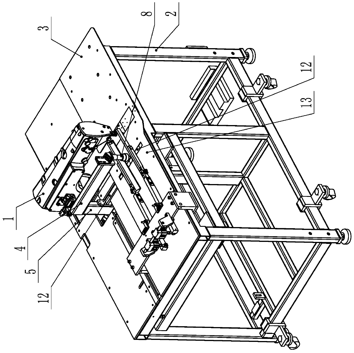
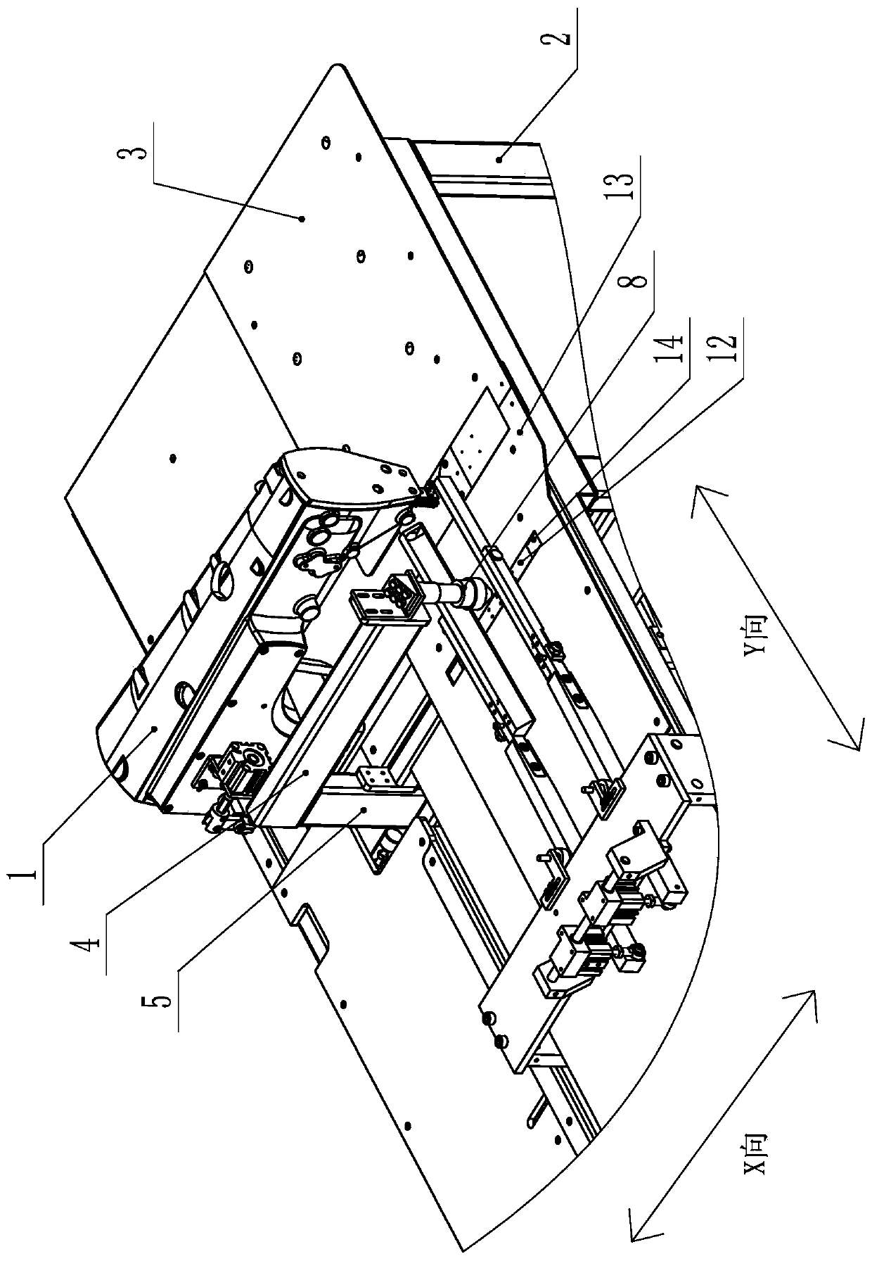
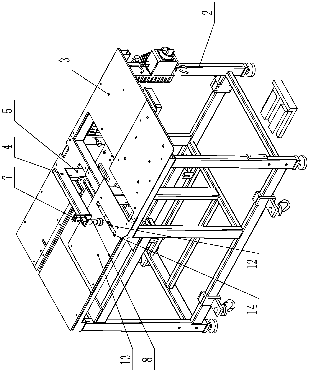
[0035] The present invention will be further described below with specific embodiment, see figure 1 -11:

[0036] A laser cutting placket machine, comprising a sewing machine head 1, a frame 2, a platen 3, a presser foot part capable of pressing the cloth and driving the cloth to move left and right, and a laser part for cutting the cloth. Be used for placing cloth on the platen 3. The sewing head 1 and the laser component are arranged on the same transmission component, and the transmission component drives the sewing head 1 and the laser component to move back and forth. The forward and backward movement in this embodiment is X-direction movement, and the left-right movement is Y-direction movement. The transmission components are arranged on the frame 1 . In the present invention, the sewing machine head 1 and the laser component are driven and moved by the same transmission component, which greatly simplifies the control mode, and the control is simpler and the cost is l...


PUM


Abstract

The invention belongs to the technical field of sewing equipment, and particularly relates to a laser cutting placket machine. The laser cutting placket machine comprises a sewing machine head, a machine rack, a platen, a presser foot component capable of pressing cloth and driving the cloth to move left and right, and a laser component used for cutting the cloth. The sewing machine head and the laser component are arranged on the same transmission component, and the transmission component is used for driving the sewing machine head and the laser component to move front and back and is arranged on the machine rack. The sewing machine head and the laser component of the laser cutting placket machine share the same driving mechanism, so that the control mode is greatly simplified, control is easier, and cost is lower.

Description

Technical field: [0001] The invention belongs to the technical field of sewing equipment, in particular to a laser cutting placket machine. Background technique: [0002] At present, the placket machines (also called openers) on the market use knives to cut the cloth, but the knives can only cut figure 1 The cutting line A shown, but the cutting line B can only be cut by hand with scissors. Manual cutting requires a high level of skill of the operator, and if there is too much cutting, the clothes will be scrapped when the sewing line is cut. In addition, manual shearing is inefficient and cannot meet market demand. In addition, when the distance between the two cutting lines needs to be changed during cutting with the cutter, it is necessary to manually adjust the cutter mechanically, which is inconvenient and wastes time. [0003] In order to improve the above phenomenon, technicians consider adding laser cutting to the placket machine. Laser cutting is the energy relea...

Claims


Application Information

Patent Timeline
Patent Type & Authority Patents(China)
IPC IPC(8): D05B37/10B23K26/38B23K26/08B23K26/142
CPCB23K26/08B23K26/142B23K26/38D05B37/10
Inventor 叶彬黄发军
Owner BULLMER ELECTROMECHANICAL TECH
Why Eureka
Try Eureka